

Electromagnetic valve
- Summary
- Abstract
- Description
- Claims
- Application Information
AI Technical Summary
Benefits of technology
Problems solved by technology
Method used
Image

Examples
Embodiment Construction
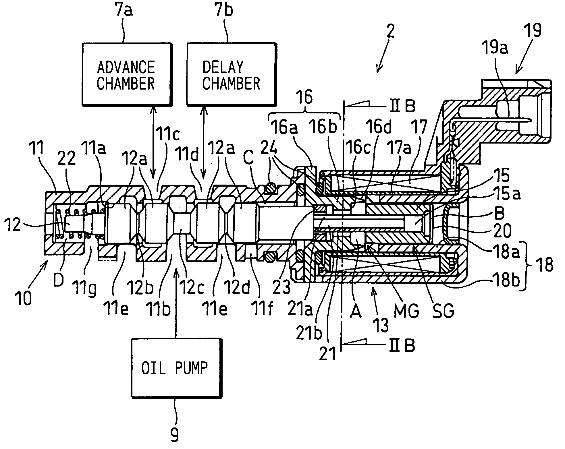
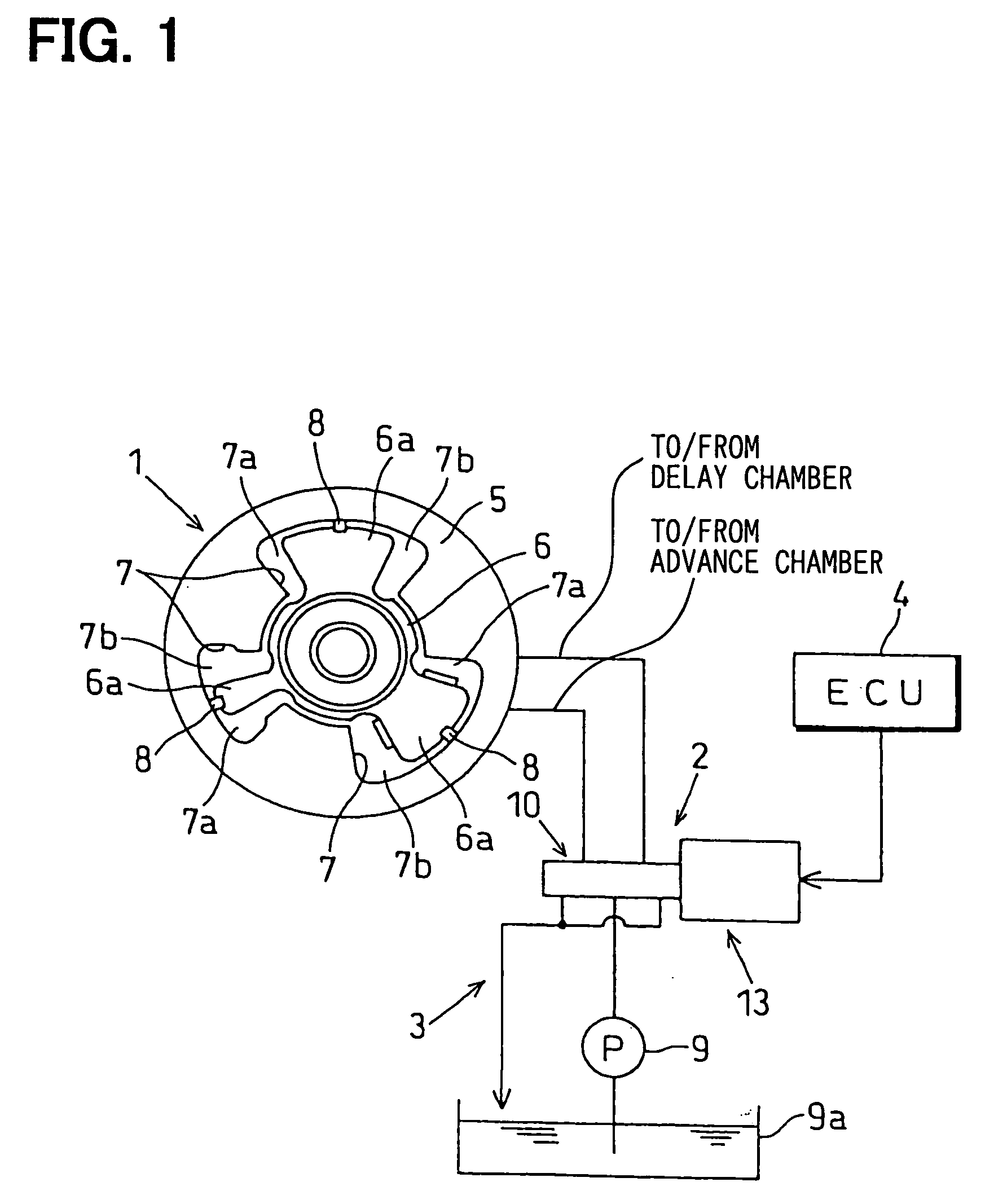
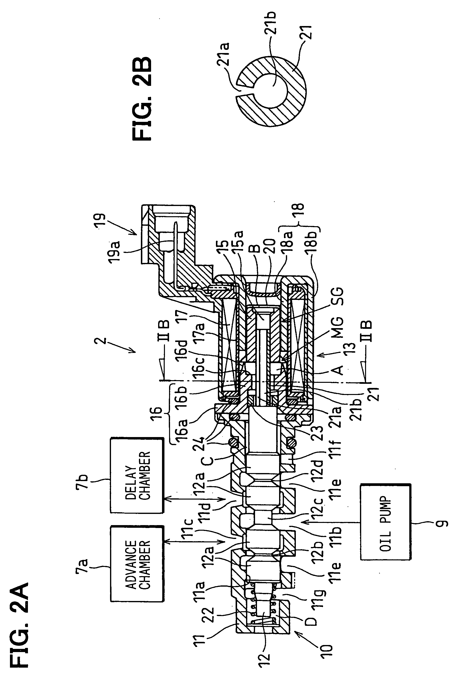
[0022] Referring to FIG. 1, a variable valve timing device (VVT) according to a first example embodiment of the present invention is illustrated.
[0023] The VVT shown in FIG. 1 is attached to a camshaft (either one of an intake valve camshaft, an exhaust valve camshaft and an intake-exhaust valve camshaft) of an internal combustion engine. The VVT can continuously vary opening-closing timing of a valve.
[0024] The VVT includes a variable cam timing mechanism (VCT) 1, an oil pressure circuit 3 including an oil flow control valve (OCV) 2, and an electronic control unit (ECU) 4 for controlling the OCV 2.
[0025] The VCT 1 includes a shoe housing (rotary driving member) 5 and a vane rotor (rotary driven member) 6. The shoe housing 5 is driven to rotate in synchronization with a crankshaft of the engine. The vane rotor 6 is provided to rotate relative to the shoe housing 5 and to rotate together with the camshaft. An oil pressure actuator provided in the shoe housing 5 drives and rotates ...
PUM
 Abstract
Description
Claims
Application Information