Using Forward-Look and Side-Look Doppler Radars for Precise Vehicle Association in Automated Traffic Surveillance

a technology of automated traffic surveillance and doppler radar, which is applied in the direction of reradiation, measurement devices, instruments, etc., can solve the problem that human errors do happen and mistakes are mad

Inactive Publication Date: 2012-07-26
HONG LANG +2
View PDF1 Cites 13 Cited by
  • Summary
  • Abstract
  • Description
  • Claims
  • Application Information

AI Technical Summary

Benefits of technology

[0007]The surveillance system may find a time when a movin

Problems solved by technology

An uncertainty arises when multiple speed readings are associated to multiple v

Method used


Image

  • Using Forward-Look and Side-Look Doppler Radars for Precise Vehicle Association in Automated Traffic Surveillance
  • Using Forward-Look and Side-Look Doppler Radars for Precise Vehicle Association in Automated Traffic Surveillance
  • Using Forward-Look and Side-Look Doppler Radars for Precise Vehicle Association in Automated Traffic Surveillance

Examples


Embodiment Construction

[0020]While the term “traffic surveillance” is used herein, it may also refer to other traffic applications, such as “traffic monitoring”, etc. The invention discussed here may be applied to the case of more than two radars.

[0021]An automated traffic surveillance system apparatus (12) is shown in FIG. 3, where 1—a forward-look Doppler radar, 5—a side-look Doppler radar which is orientated with a certain angle away from the forward-look Doppler radar, 9—a data processing unit, 10—a data recording unit, and 11—a display unit. Two approaching vehicles (2 and 4) move from inside of the forward-look Doppler radar energy beam (3) at time instant k into the side-look Doppler radar energy beam (6) at time instant (k+T).

[0022]FIGS. 4 and 5 present different operation and time regions in the forward-look and side-look Doppler radars. As an approaching vehicle moves from the forward-look Doppler radar energy beam (3) into the side-look Doppler radar energy beam (6), the famous Doppler radar co...


PUM


Abstract

This invention is related to an automated traffic surveillance system to monitor traffic comprising of a plural number of Doppler radars, circuitry for processing radar signals, and data recording and displaying devices. Although the system is mainly designed for roadside traffic surveillance, it can be used in different applications, such as mounted on a host vehicle. The system will provide continuous surveillance of all incoming and leaving traffic.

Description

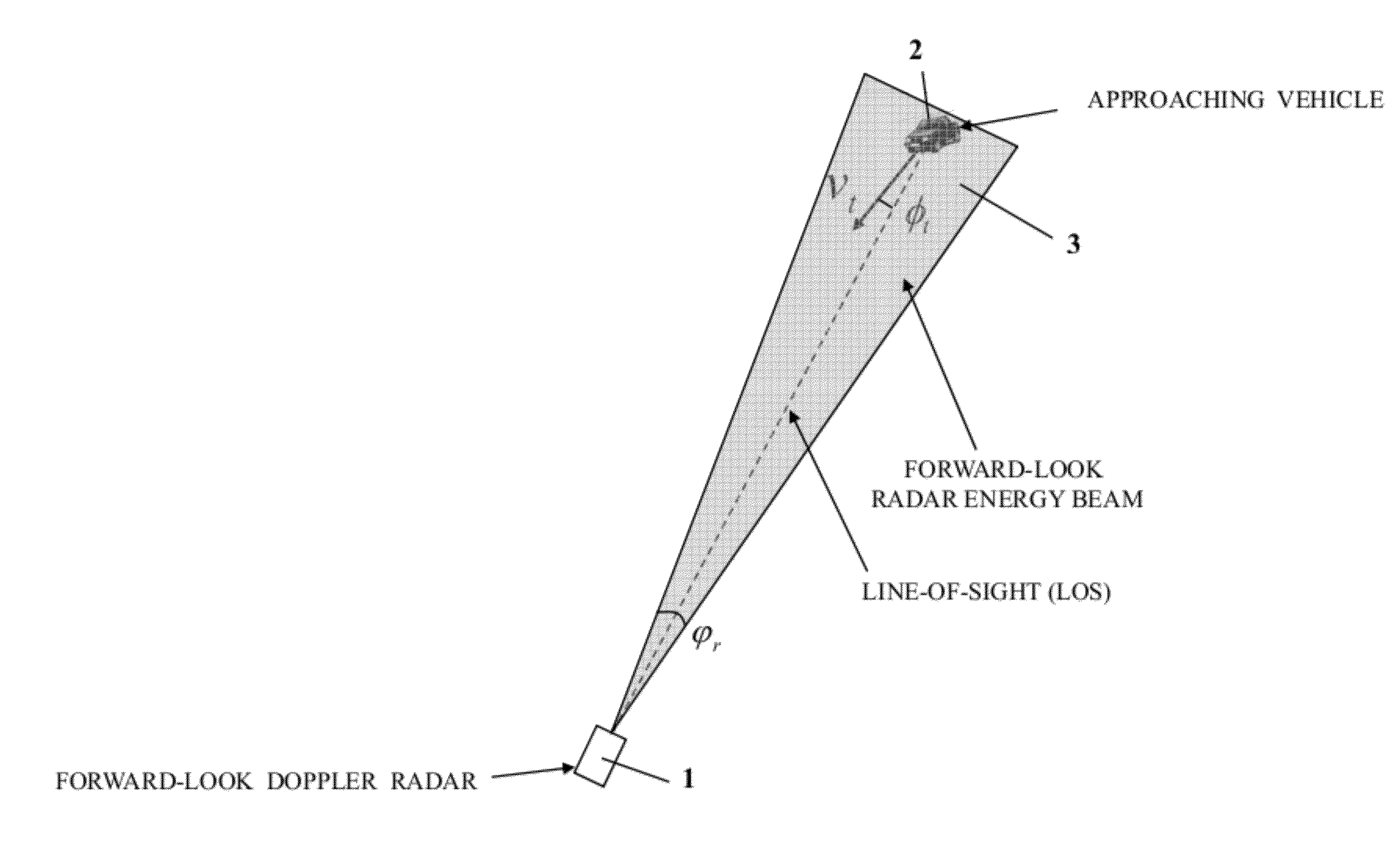
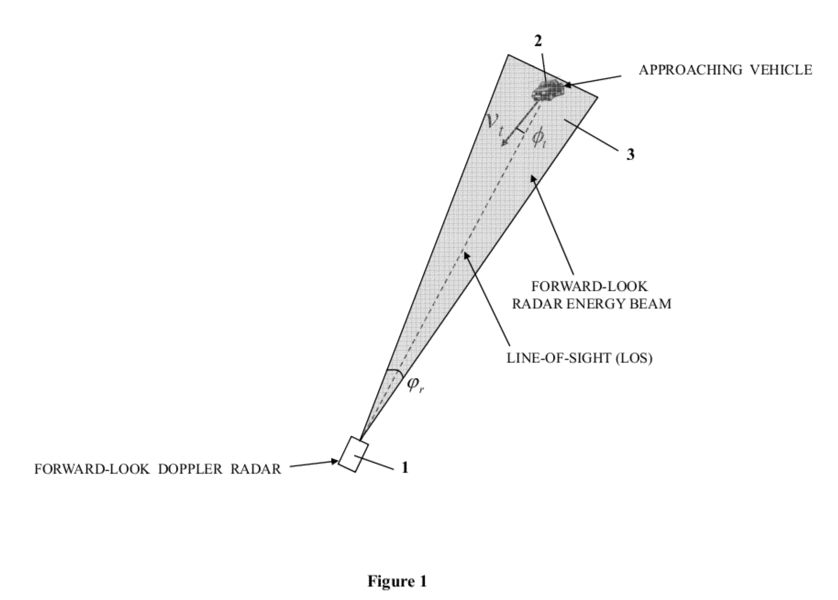
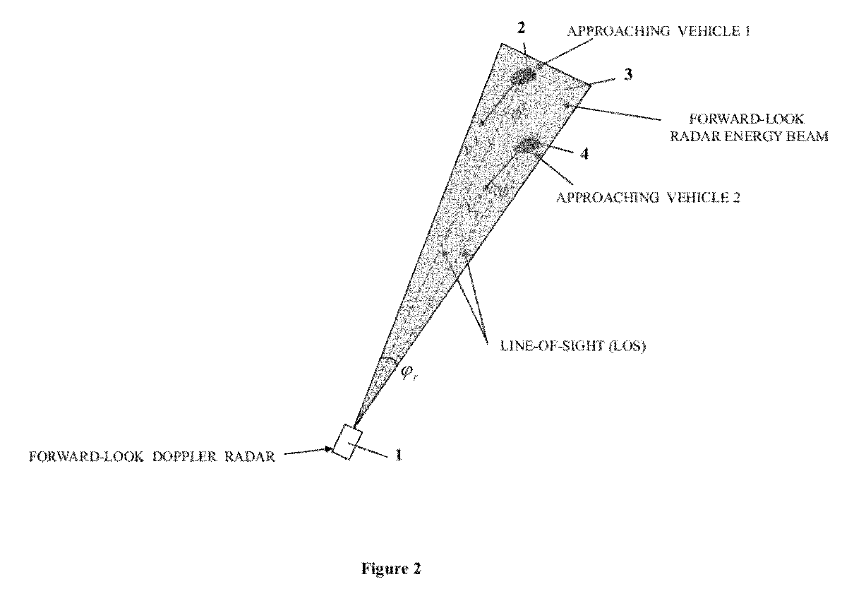
TECHNICAL FIELD[0001]This invention relates to Using Forward-Look and Side-Look Doppler Radars for Precise Vehicle Association in Automated Traffic Surveillance.BACKGROUND OF THE INVENTION[0002]Traditional Doppler radar traffic surveillance scenario: In a traditional Doppler radar traffic surveillance scenario, a Doppler radar is aiming at the traffic flow, as shown in FIG. 1 (the forward-look Doppler radar in FIG. 1), which measures a vehicle speed at line-of-sight (LOS). In FIG. 1, the speed of an approaching (or a leaving) vehicle is calculated in terms of Doppler frequency fD byvt=fDKcos(φt)(1)where K is a Doppler frequency conversion constant and φt is the angle between the vehicle velocity vector vt and the LOS. In a traditional traffic surveillance scenario, φt is less than 10 degrees, so cos(φt)≠1 andvt≈fDK.(2)However, because the radar energy beam angle, φr in FIG. 1, is not small (typically 12 degrees), several vehicles could be illuminated simultaneously by a radar energy...

Claims


Application Information

Patent Timeline
IPC IPC(8): G01S13/58
CPCG08G1/052G01S13/92
Inventor HONG, LANGHONG, STEVEN SIYINGYANG, WU
Owner HONG LANG
Why Eureka
Try Eureka