Image processing method and image processing apparatus

a processing method and image technology, applied in the field of serial type inkjet printing apparatus, can solve the problems of image degradation, increased number of main scans needed for completing an image, and increased time for printing

Active Publication Date: 2012-07-26
CANON KK
View PDF4 Cites 13 Cited by
  • Summary
  • Abstract
  • Description
  • Claims
  • Application Information

AI Technical Summary

Problems solved by technology

When there is fluctuation in conveyance amount during a plurality of conveyance operations while printing, seam lines such as white stripes or black stripes between the images (between bands) that are printed in each scan occur, which causes the image to become degraded.
However, on the other hand, the number of main scans necessary for completing an image also increases, so more time is required for printing.
However, even though the method disclosed in Japanese Patent No. 4,217,651 is effective in reducing the state of seam lines predicted from the printing duty, this method is not able to avoid black stripes or white stripes that suddenly appear due to fluctuations in the conveyance operation.
In addition, in the method disclosed in Japanese Patent No. 4,217,651, it is possible to adjust how noticeable seam lines will be within the controllable range of the conveyance amount, however, it is not able to handle small seam lines that occur due to error in the conveyance amount.

Method used


Image

  • Image processing method and image processing apparatus
  • Image processing method and image processing apparatus
  • Image processing method and image processing apparatus

Examples


embodiment 1

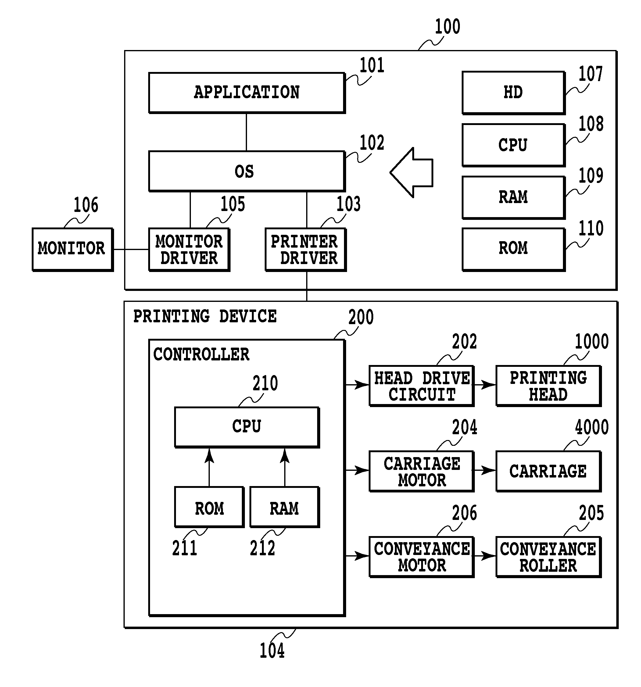
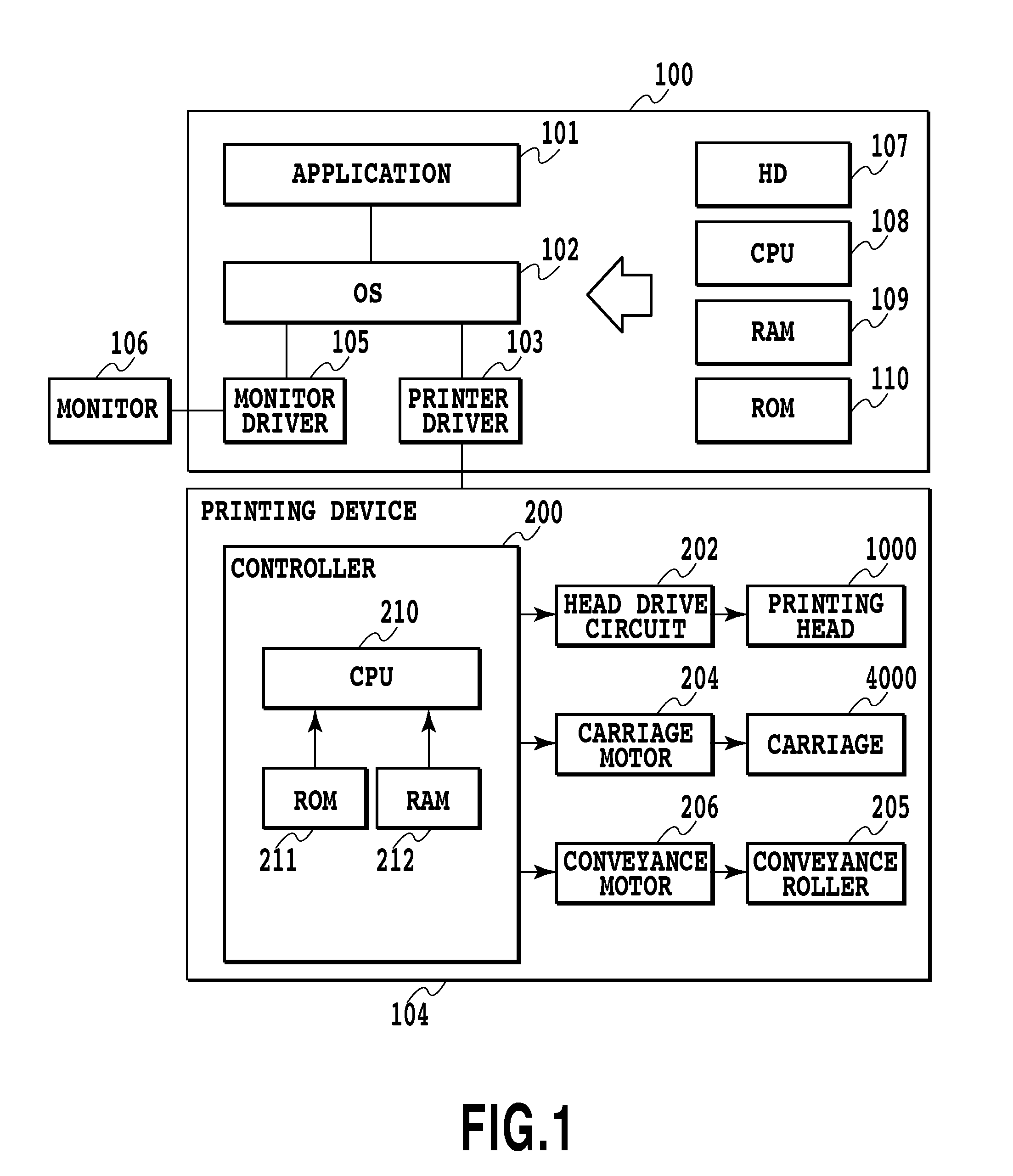
[0031]FIG. 1 is a block diagram illustrating the construction of a host device 100 and printing apparatus 104 of a printing system to which the present invention can be applied. A CPU 108, via an operating system 102, operates each of the software of an application 101, printer driver 103 and monitor driver 105 according to various programs stored in a hard disk (HD) 107 or ROM 110. When doing this, a RAM 109 is used as a work area when executing various processes. The monitor driver 105 is software for executing processing such as creating image data to be displayed on the monitor 106. The printer driver 103 is software for converting image data that is sent from the application software 101 to the OS 102 to image data that can be received by the printing apparatus 104, and after that transmitting that image data to the printing apparatus 104.

[0032]On the other hand, a controller 200, a printing head 1000, a head drive circuit 202, a carriage 4000, a carriage motor 204, a conveyanc...

embodiment 2

[0080]In this embodiment as well, the image printing system, printing apparatus and printing head that were explained in FIG. 1 to FIG. 4 are used. Image data is also processed so that the number of dots there are in boundary portions increases as the printing duty becomes higher. However, in this embodiment, instead of using dot arrangement patterns and mask patterns in order to achieve this kind of image processing, a seam correction process that is unique to this embodiment is provided between the pre-processing J0002 and post-processing J0003 in the printer driver.

[0081]FIG. 17 is a flowchart for explaining the process of the printer driver executing the seam correction process of this embodiment. First, in step S1, RGB values are inputted from pre-processing J0002, then in step S2, it is determined whether or not the input data is pixel data corresponding to boundary portions. When it is determined that the input data does not correspond to boundary portions, processing jumps t...


PUM


Abstract

Provided is an image processing apparatus and image processing method that are capable of outputting an image wherein seam lines caused by sudden conveyance error are difficult to notice even for a small number of multi passes printing. In order to achieve this, the number of dots that are printed in pixels is adjusted according to the density level so that the number of dots that are printed in pixels corresponding to boundary portions is larger than in pixels corresponding to areas that are not boundary portions, and so that the number of dots that are printed in pixels corresponding to boundary portions increases the higher the density level of the pixels is. As a result, it is possible to avoid the occurrence of white stripes in high-density areas without emphasizing black stripes in low-density areas.

Description

BACKGROUND OF THE INVENTION[0001]1. Field of the Invention[0002]The present invention relates to a serial type inkjet printing apparatus. The invention particularly relates to an image processing method and image processing apparatus for reducing the bad effects of seam lines that appear at the boundary portions for each printing scan in a serial type printer.[0003]2. Description of the Related Art[0004]In a serial type inkjet printer, images are gradually printed by alternately repeating a main scan of moving while discharging ink, and a conveyance operation of conveying a printing medium in a direction crossing to the main scan. When there is fluctuation in conveyance amount during a plurality of conveyance operations while printing, seam lines such as white stripes or black stripes between the images (between bands) that are printed in each scan occur, which causes the image to become degraded. For example, when the conveyance amount of printing medium becomes greater than a spec...

Claims


Application Information

Patent Timeline
Patent Type & Authority Applications(United States)
IPC IPC(8): G06K15/02
CPCG06K15/1874G06K15/107
Inventor MARUMOTO, YOSHITOMOTSUBOI, HITOSHIUSHIYAMA, TAKAYUKI
Owner CANON KK
Why Eureka
Try Eureka