Flexible neural localization devices and methods

a neural localization and flexible technology, applied in the field of flexible devices, can solve the problems of inability to accurately guide surgical procedures, risk damage to nerve tissue, and system variability, and achieve the effect of reducing the risk of nerve damag

a neural localization and flexible technology, applied in the field of flexible devices, can solve the problems of inability to accurately guide surgical procedures, risk damage to nerve tissue, and system variability, and achieve the effect of reducing the risk of nerve damag

US20120191003A1Inactive Publication Date: 2012-07-26AMENDIA

Image

  • Flexible neural localization devices and methods
  • Flexible neural localization devices and methods
  • Flexible neural localization devices and methods

Examples


integrated embodiments

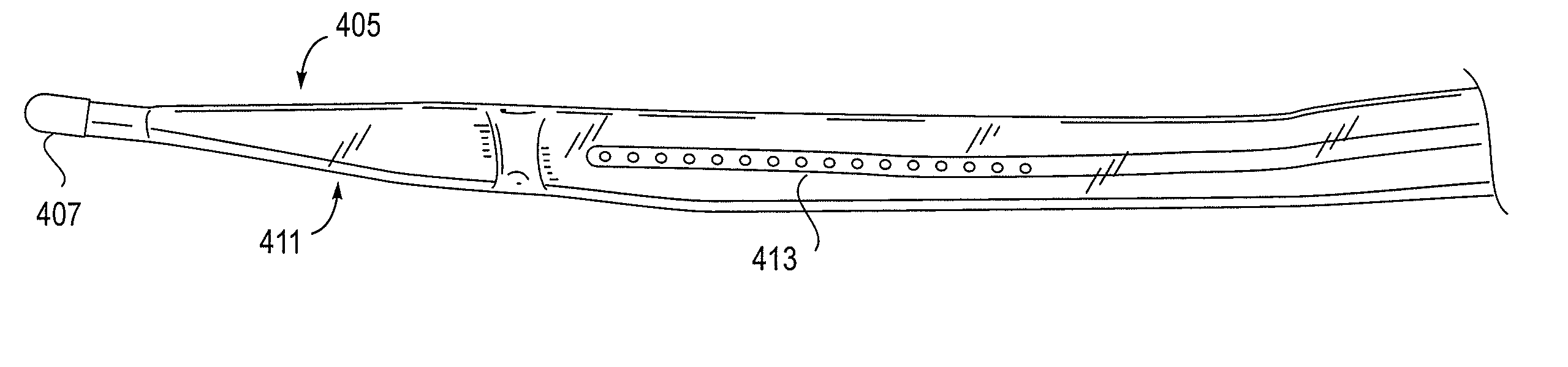
[0249]As mentioned above, the NLR device described herein may couple to one or more tissue modification devices. FIGS. 20A and 20B illustrate two examples of NLR devices 2000 that are configured to couple to tissue modification devices 2001. In FIG. 20A, the tissue modification device 2001 is an elongate flexible tissue removal device that includes tissue modification elements 2003 (e.g., “teeth”) on one side, and has a coupling element at the distal end 2005. The coupling element may be a guidewire coupler, or it may be configured to couple directly to an NLR device 2000. The NLR device 2000 (shown adjacent to the distal end of the tissue modification device in FIG. 20A) includes an opening or cavity into which the tissue modification device may at least partially enter and engage. In other variations, the proximal end of the NLR device is configured to couple to the distal end of the tissue modification device without entering the NLR device.

[0250]The NLR device in this example ma...


PUM


Abstract

Described herein are bimanually controlled neural localization devices capable of determining if a nerve is nearby a region of the device. In general, the device may include at least two electrodes including an anode in electrical communication with a anodal conductor and a cathode in electrical communication with a cathodal conductor. The device may further include a flexible elongate body, wherein the flexible elongate body has an axial length, a width and a thickness, wherein the axial length is greater than the width, and the width is greater than the thickness and is greater than a width of the at least two electrodes. The at least two electrodes may be disposed substantially in-line and centered along the length of the elongate body. In some embodiments, the device may further include a guidewire coupler at the distal end region of the elongate body.

Description

CROSS REFERENCE TO RELATED APPLICATIONS[0001]This patent application claims the benefit of U.S. Provisional Patent Application No. 61 / 470,303, titled “TISSUE MODIFICATION DEVICES AND METHODS”, filed on Mar. 31, 2011; U.S. Provisional Patent Application No. 61 / 470,802, titled “TISSUE MODIFICATION DEVICES AND METHODS”, filed on Apr. 1, 2011; and U.S. Provisional Patent Application No. 61 / 488,762, titled “NEURAL LOCALIZATION DEVICES AND METHODS”, filed on May 22, 2011; each of which is incorporated by reference in its entirety.[0002]This patent application is also a continuation-in-part to U.S. patent application Ser. No. 13 / 340,363, titled “FLEXIBLE NEURAL LOCALIZATION DEVICES AND METHODS”, filed on Dec. 29, 2011; which is a continuation-in-part to U.S. patent application Ser. No. 12 / 724,315, titled “FLEXIBLE NEURAL LOCALIZATION DEVICES AND METHODS”, filed on Mar. 15, 2010, now Publication No. US-2011-0004207-A1; which is a continuation-in-part to U.S. patent application Ser. No. 12 / 5...

Claims


Application Information

Patent Timeline
26 Jul 2012
Publication
US20120191003A1
IPC
A61B5/05
CPC
A61B5/04001; A61B2017/32006; A61B5/1107; A61B5/4519; A61B5/4893; A61B17/1671; A61B17/1757; A61B17/7092
Inventors
GARABEDIAN, ROBERT; SUN, BENJAMIN KAO-SHING