Hearing testing probe apparatus with digital interface

a technology of hearing testing and digital interface, which is applied in the field of hearing testing probes, can solve the problems of compromising the accuracy of assessment, the inability to perform repeatable and consistent measurements with currently available commercial hearing testing probes, and the less accurate current calibration methods

Active Publication Date: 2012-07-26
INTERACOUSTICS
View PDF2 Cites 19 Cited by
  • Summary
  • Abstract
  • Description
  • Claims
  • Application Information

AI Technical Summary

Problems solved by technology

Current calibration methods become less accurate as the frequency of the desired stimulus increases.
While it is desirable to perform measurements at higher frequencies, where often the first indications of hearing loss would be present, the ability to perform repeatable and consistent measurements with currently available commercial hearing testing probes is significantly limited.
Assessment and diagnosis of the test responses are based on the levels of the stimulus applied, and thus the accuracy of the assessment is compromised if the applied levels are not accurate.
The accuracy of the calibration with the commonly available hearing test probes is limited by an intentional design feature.
This recess, usually two to three millimeters in length, provides a place for contamination (e.g., cerumen or other biological material) to collect without entering the body of the probe where cleaning or extraction of the contamination would be difficult and can compromise the performance of the probe.
However, the recessed tip design is not desirable for performing hearing testing at high frequencies because of known errors in performing calibration at high frequencies associated with recessed probe tips.
However, the cost of the replacement component can be significant even though it is only likely to require replacement after the testing of numerous subjects.
This problem would be significantly exacerbated if the probe end is designed to exit flush with, or extend slightly beyond, the end of the eartip.
As noted above, the recessed tip design is not desirable for performing hearing testing at high frequencies because of known errors in performing calibration at high frequencies associated with recessed probe tips.
Additionally, existing replacement probe tips are too expensive and cumbersome to replace frequently.
Another limitation in current hearing probe designs is the minimal area available for the stimulus and microphone acoustic channels through the eartip.
A three millimeter outer diameter limitation is the industry standard such that the eartips are small enough to properly fit and seal to the ear canals of infants and newborns.
This minimal cross-sectional area of the stimulus and microphone channels causes limitations in the frequency response of the stimulus sources and increases the impedance of the microphone input which causes an increase in its noise floor.
As such, these existing hearing test devices have been limited to performing a hearing test on one ear at a time.
Also, existing hearing test instruments have been limited in the manner of communication between the probe and the instrument.
However, the cables used in existing hearing test instruments have limited cable lengths, requiring the patient and tester to be in close proximity and reducing flexibility in probe placement.
The construction of this communication cable is complicated by the requirement to eliminate interference between the stimulus channels and the microphone channel.
The probe cable adds bulk and weight to the system and may pull on the probe in the ear during testing, making it difficult to keep the required seal and positioning in the ear canal.

Method used


Image

  • Hearing testing probe apparatus with digital interface
  • Hearing testing probe apparatus with digital interface
  • Hearing testing probe apparatus with digital interface

Examples


Embodiment Construction

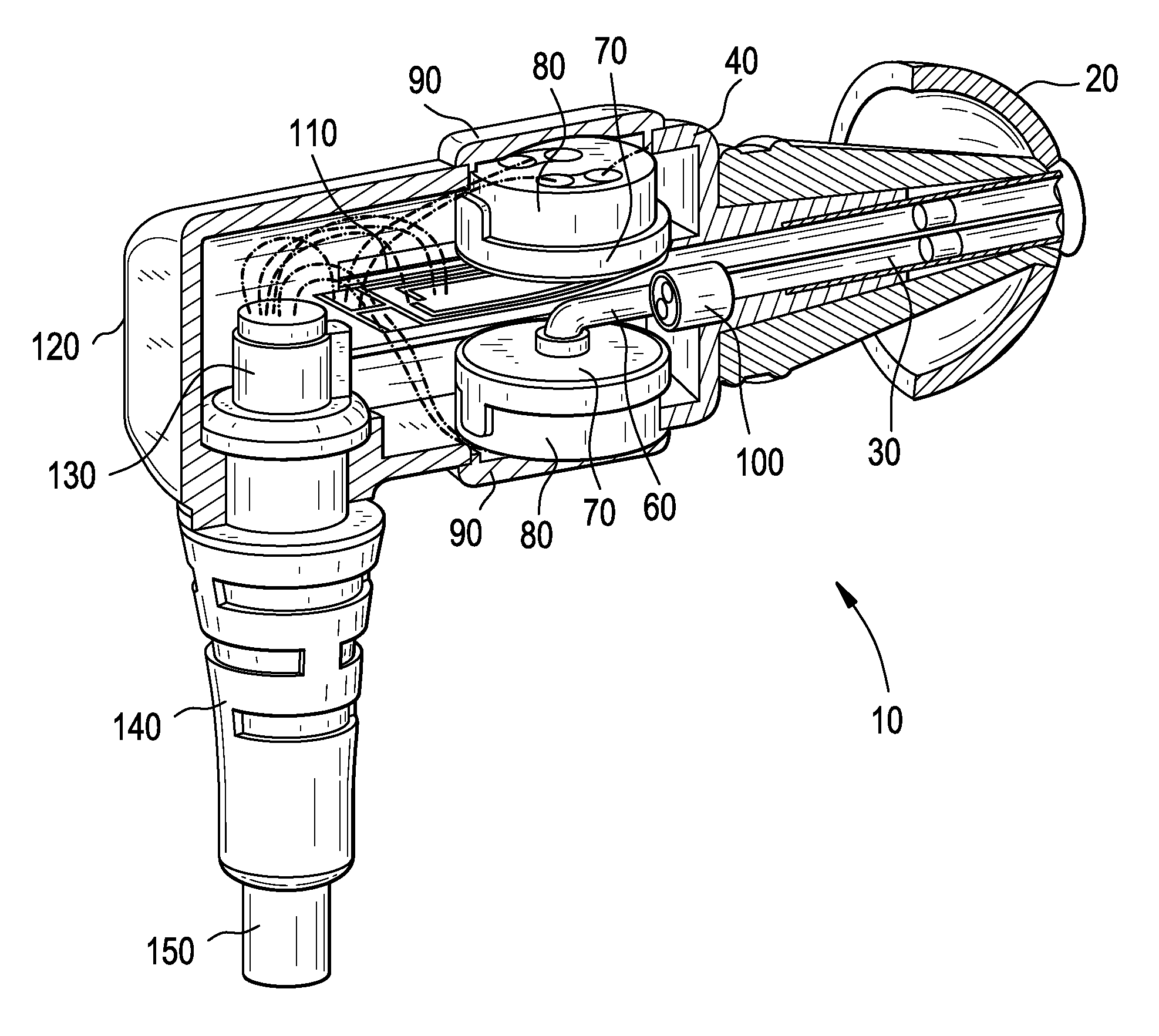
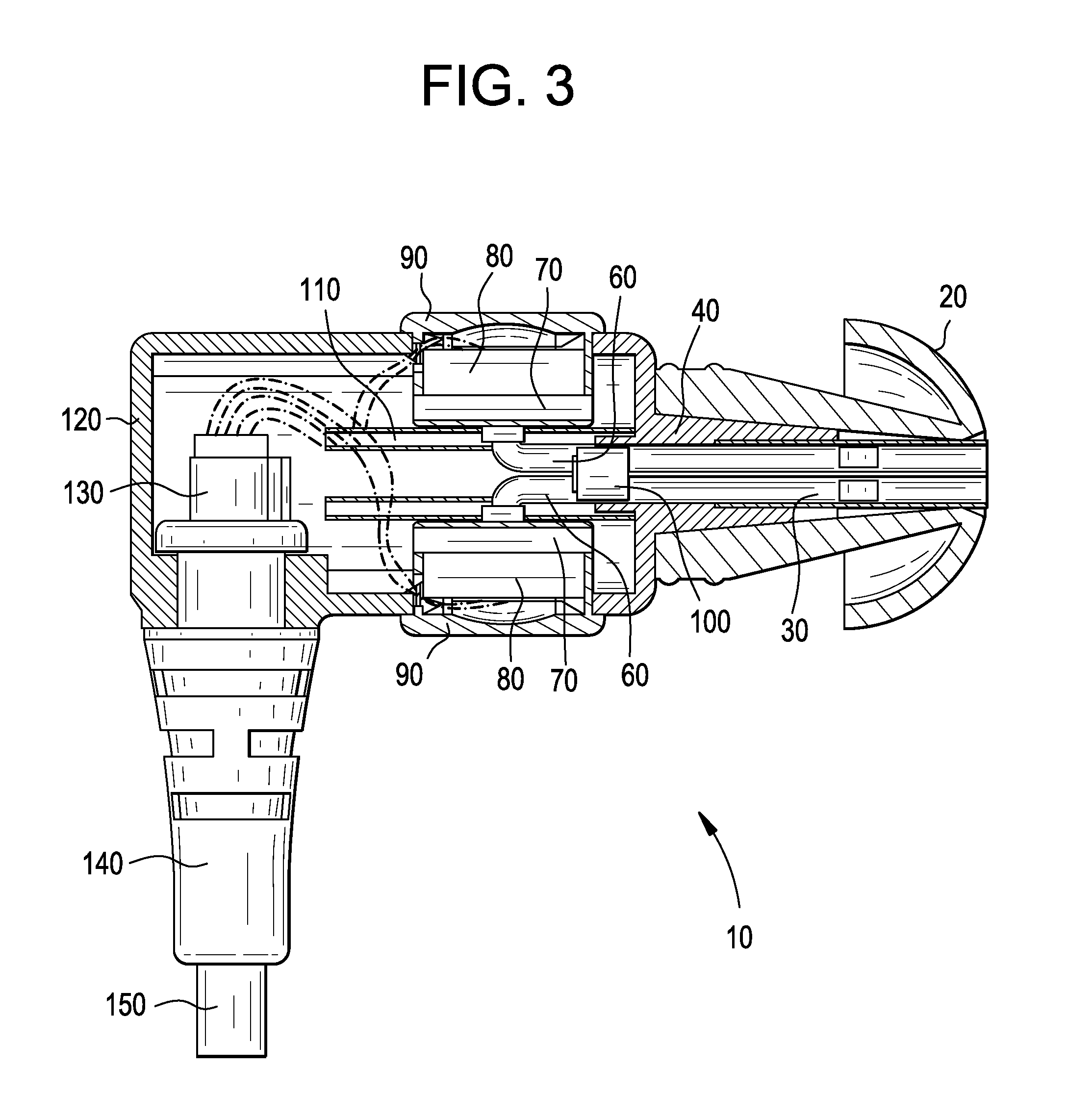
[0041]Embodiments of the present technology provide a hearing testing probe with a user-replaceable coupling member for interfacing to an ear canal. Embodiments of the present technology provide hearing testing probes placed within ear canals that are coupled via a digital interface to an instrument that monitors the condition within the ears.

[0042]FIGS. 3-4 and 7-8 illustrate side views in cross-section of exemplary embodiments of the hearing test probe 10 used in accordance with an embodiment of the present technology. FIGS. 5 and 9 illustrate exploded side views of exemplary embodiments of the hearing test probe 10. FIG. 14 illustrates a view of an exemplary hearing testing probe 10 and probe tube 30 used with an elastomeric eartip 20. FIG. 15 illustrates a view of an exemplary hearing testing probe 10 and probe tube 30 with an adhered to eartip 20.

[0043]Referring to FIGS. 3-5, 7-9 and 14-15, certain embodiments of a hearing testing probe 10 include a cable 150 for communicating ...


PUM


Abstract

Certain embodiments provide a hearing testing probe apparatus. The hearing testing probe apparatus includes a probe tube detachably coupled at a first end to a probe body and extending through a center hole in an eartip to align proximate a face of the eartip at a second end. The probe tube includes a plurality of stimulus lumens for receiving and carrying stimulus from the first end of the probe tube for output at the second end of the probe tube. The probe tube includes one or more microphone lumens for receiving and carrying one or more measured responses from the second end of the probe tube to one or more microphones at the first end of the probe tube.

Description

CROSS-REFERENCE TO RELATED APPLICATIONS / INCORPORATION BY REFERENCE[0001]The present application claims priority under 35 U.S.C. §119(e) to provisional application Ser. No. 61 / 435,620, filed on Jan. 24, 2011.[0002]The above referenced provisional application is hereby incorporated herein by reference in its entirety.FEDERALLY SPONSORED RESEARCH OR DEVELOPMENT[0003]This invention was made with government support under contract number N00014-10-M-0267 awarded by the Office of Naval Research. The government has certain rights in the invention.MICROFICHE / COPYRIGHT REFERENCE[0004][Not Applicable]BACKGROUND OF THE INVENTION[0005]The present invention relates generally to hearing testing probes placed within ear canals that are coupled to an instrument that monitors the condition within the ears. More specifically, the present invention provides a hearing testing probe with a user-replaceable coupling member for interfacing to an ear canal. The present invention further relates generally to...

Claims


Application Information

Patent Timeline
Patent Type & Authority Applications(United States)
IPC IPC(8): A61B5/12
CPCA61B5/6817A61B5/121A61B5/125
Inventor ISEBERG, STEVEKILLION, MEAD C.DRAMBAREAN, VIORELMAPES-RIORDAN, DANSIEGEL, JONATHANDHAR, SUMITRAJITVIRANYI, STEVE
Owner INTERACOUSTICS
Why Eureka
Try Eureka