Scalable call stack sampling

a call stack and call stack technology, applied in the field of computing environment, can solve the problems of affecting the analysis of production environment, affecting the quality of application data,

Inactive Publication Date: 2012-07-26
IBM CORP
View PDF11 Cites 31 Cited by
  • Summary
  • Abstract
  • Description
  • Claims
  • Application Information

AI Technical Summary

Problems solved by technology

However, trying to figure out bottlenecks or why workloads are not scaling may involve hundreds or thousands of threads that are not executing.
Getting information on all threads or all threads that are not executing

Method used


Image

  • Scalable call stack sampling
  • Scalable call stack sampling
  • Scalable call stack sampling

Examples


Embodiment Construction

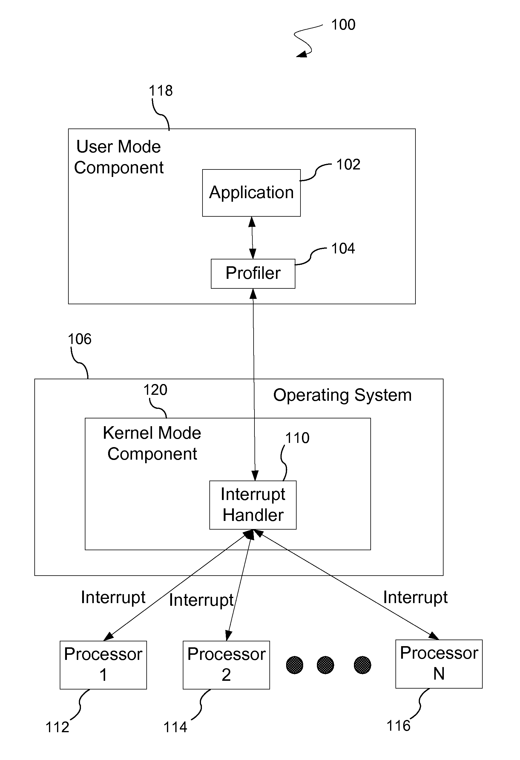
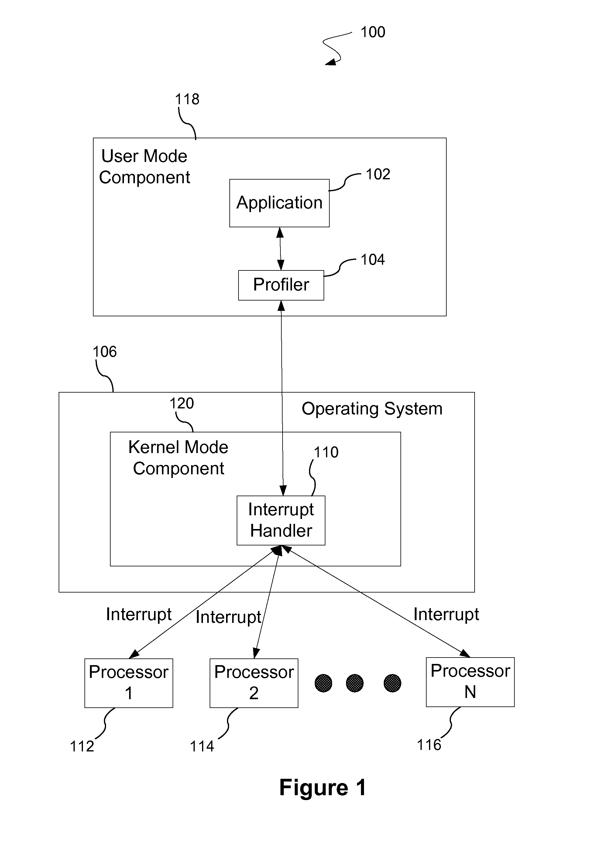
[0016]With the increase in Web applications that support the processing of requests from many client machines, analysis and resolution of the causes of bottlenecks where requests are not being processed as quickly as needed are helpful. Performance bottlenecks may have various causes. For example, the root cause of a bottleneck may be caused by a resource not being available to allow the required work to continue. For instance, a thread may be waiting for input / output (“I / O”) to complete or for some other resource to become available. In a common case, access to an internal data structure that is currently being locked for access by another thread may be helpful. Further, one or more threads that are not currently being executed may need to perform some work to meet the demands of the work loads. These conditions may occur even when processors are available to perform additional work, i.e., when processors are not being used or “idle.” With computer hardware adding more processing c...


PUM


Abstract

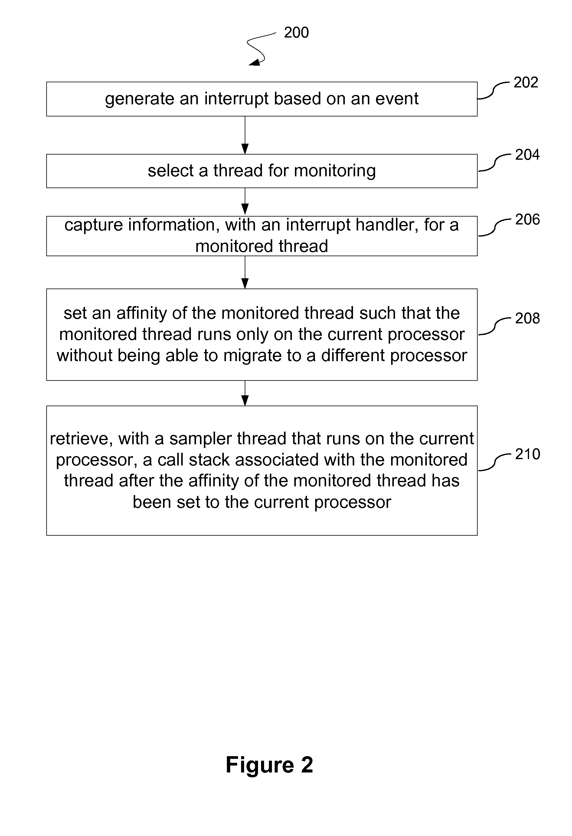
An interrupt is generated based on an event. Further, a thread is selected for monitoring. In addition, an interrupt handler captures information for the monitored thread. An affinity of the monitored thread is set such that the monitored thread runs only on a current processor without being able to migrate to a different processor. A sampler thread that runs on the current processor retrieves a call stack associated with a monitored thread after the affinity of the monitored thread has been set to the current processor.

Description

BACKGROUND[0001]1. Field[0002]This invention generally relates to a computing environment. More particularly, the invention relates to sampling technology.[0003]2. General Background[0004]Either time-based or hardware event-based sampling technology is typically utilized in application profiling tools to determine the specific usage of resources. A current approach is to sample by periodically generating interrupts. At each interrupt the current process / thread, the instruction being executed and, optionally, the data address being accessed, may be identified and recorded. At a later time, the collected data is aggregated, and reports are generated showing sample distribution by address, symbol, process, etc. A variety of tools are based on this technology. The full execution context of the sample is not typically recorded and not available in reports.[0005]Attempts have been made to improve this technology by getting call stacks at the time of the sample. The existing set of tools m...

Claims


Application Information

Patent Timeline
IPC IPC(8): G06F13/24
CPCG06F13/24G06F9/4812
Inventor KUIPER, KEAN G.LEVINE, FRANK E.
Owner IBM CORP
Why Eureka
Try Eureka