
Surgical Fastener Applying Apparatus

a technology of fastener and application apparatus, which is applied in the field of surgical stapling instruments, can solve the problems of unfavorable obtaining of equal gap distance, limited backspan of aforementioned staples, and a chance of bleeding and leakage at the stapled tissue line, so as to facilitate formation

Active Publication Date: 2012-08-02
TYCO HEALTHCARE GRP LP
View PDF6 Cites 183 Cited by
  • Summary
  • Abstract
  • Description
  • Claims
  • Application Information

AI Technical Summary

Benefits of technology

[0014]The surgical stapler may have a second annular array of staples and a corresponding second annular array of staple forming buckets, wherein the second annular array of staple forming buckets includes a depth that is less than a depth of the first annular array of staple forming buckets. The formed staples of the second annular array of staples may be crimped to provide a second compressive space that is different than the first compressive space.
[0015]In another aspect, a surgical stapler comprises: a tubular body portion; a cartridge assembly disposed at a distal end of the body portion for expelling a first annular array of staples, each of the s

Problems solved by technology

These unequal gap distances are not conducive to obtaining a “tight” staple line.
Unfortunately, the length of the backspan of the aforementioned staples is limited by geometry from interfering with, i.e., extending into, the next row of staples.
As a result thereof, subsequent to tissue being stapled with conventional surgical stapling devices, there exists a chance of bleeding and leakage occurring at the stapled tissue line, i.e., adjacent the area between consecutive staples in the annular array of staples in the outer annular array(s).
Or, in certain instance, a compromised stapled tissue line being formed, which, in turn, may result in the stapled tissue separating.

Method used


Image

  • Surgical Fastener Applying Apparatus
  • Surgical Fastener Applying Apparatus
  • Surgical Fastener Applying Apparatus

Examples


Embodiment Construction

[0038]Detailed embodiments of the present disclosure are disclosed herein; however, the disclosed embodiments are merely examples of the disclosure, which may be embodied in various forms. Therefore, specific structural and functional details disclosed herein are not to be interpreted as limiting, but merely as a basis for the claims and as a representative basis for teaching one skilled in the art to variously employ the present disclosure in virtually any appropriately detailed structure.

[0039]In the drawings and in the descriptions that follow, the term “proximal,” as is traditional, will refer to the end of a surgical instrument that is closer to the user, while the term “distal” will refer to the end of the surgical instrument that is farther from the user.

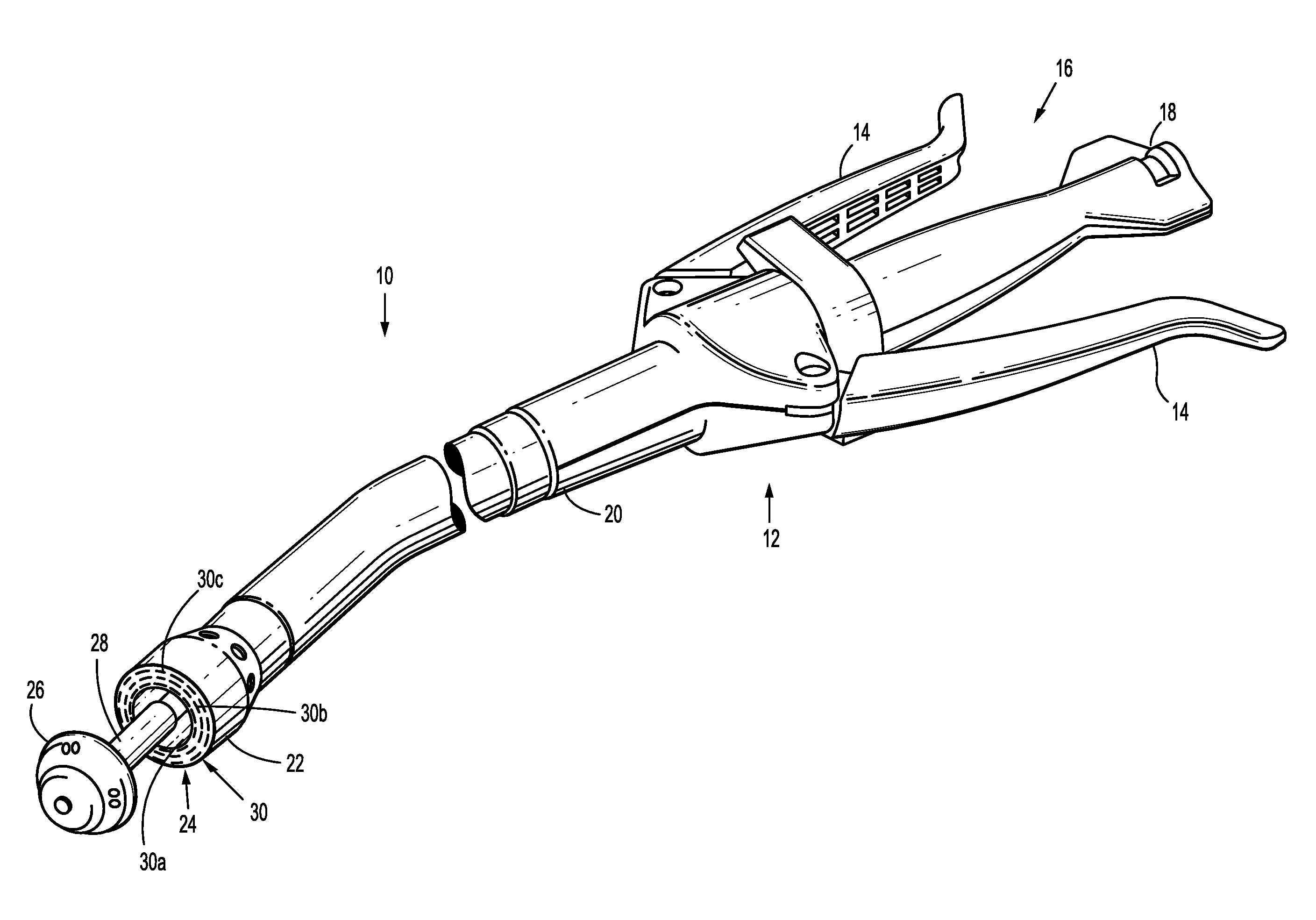
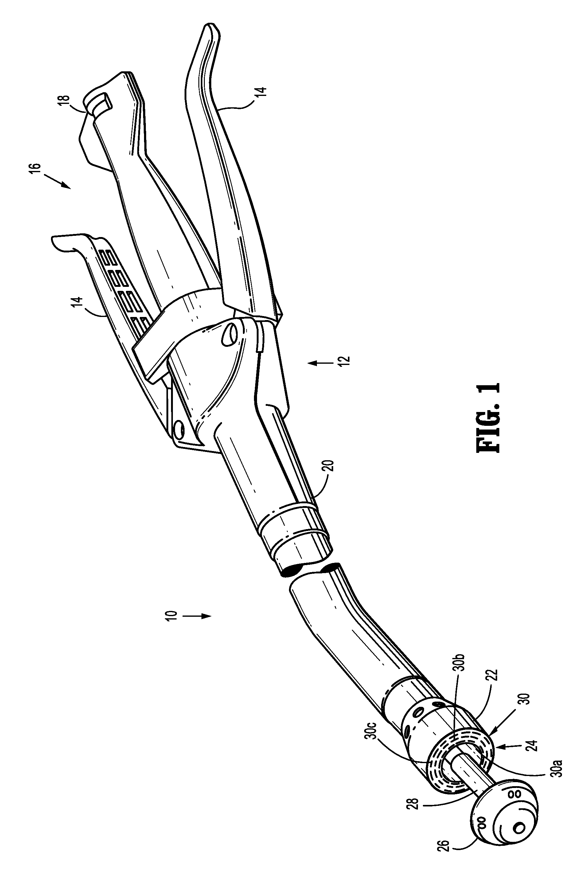
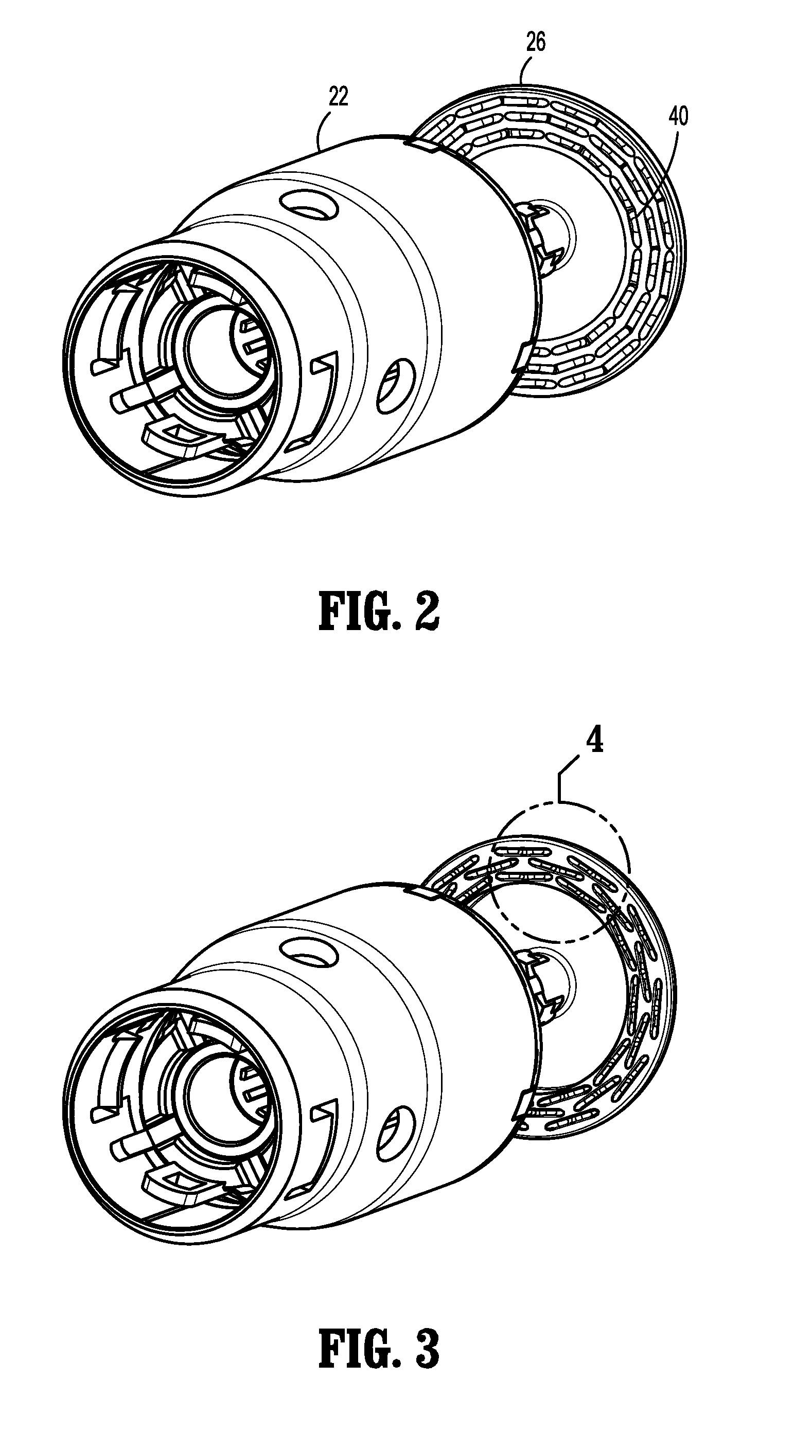
[0040]Referring now in specific detail to the drawings, in which like reference numerals identify similar or identical elements throughout the several views, FIG. 1 shows a surgical stapling apparatus 10 (apparatus 10) in acc...


PUM

PropertyMeasurementUnit
Lengthaaaaaaaaaa
Depthaaaaaaaaaa
Compressive stressaaaaaaaaaa

Abstract

A surgical stapler is provided. The stapler includes a tubular body portion. A cartridge assembly is disposed at a distal end of the body portion for expelling an annular array of staples. Each of the staples of the annular array of staples has a generally bent backspan. An anvil member disposed at the distal end of the tubular body portion is positioned opposite the cartridge assembly to clinch the staples in tissue upon expulsion of the staples from the cartridge assembly. The anvil member has a corresponding annular array of staple forming buckets. Each of the buckets is configured to accommodate the generally bent configuration of the staples to facilitate formation thereof.

Description

CROSS-REFERENCE TO RELATED APPLICATIONS[0001]The present application is a continuation-in-part of U.S. patent application Ser. No. 13 / 207,653 filed on Aug. 11, 2011, which claims benefit of U.S. Provisional Application No. 61 / 388,788 filed on Oct. 1, 2010, which claims benefit of U.S. Provisional Application No. 61 / 410,980 filed on Nov. 8, 2010, the entire contents of which is hereby incorporated by reference.BACKGROUND[0002]1. Technical Field[0003]The present disclosure relates to surgical stapling instruments for applying surgical fasteners or staples to body tissue and, more particularly to surgical stapling instruments utilizing bent backspan staples and having a corresponding anvil including bent staple forming buckets.[0004]2. Description of Related Art[0005]Surgical stapling devices for applying an annular array of staples or fasteners to tissue are well known in the art. For example, such surgical stapling devices have particular utility in performing small bowl resection wi...

Claims


Application Information

Patent Timeline
IPC IPC(8): A61B17/068
CPCA61B17/0644A61B2017/07264A61B2017/07235A61B17/1155A61B17/068A61B17/105
Inventor WILLIAMS, JUSTINPENNA, CHRISTOPHERSCIRICA, PAULRACENET, DAVID
Owner TYCO HEALTHCARE GRP LP
Learn More