
Antenna array and method for operating antenna array

a technology of antenna array and antenna array, applied in the field of antenna array, can solve problems such as loss of flexibility

Active Publication Date: 2012-08-02
TELEFON AB LM ERICSSON (PUBL)
View PDF2 Cites 93 Cited by
  • Summary
  • Abstract
  • Description
  • Claims
  • Application Information

AI Technical Summary

Benefits of technology

The present patent is about an active antenna array with multiple antenna elements. The array has two subsets of antenna elements that relay different radio signals with specific beam patterns. One of the antenna elements is a common element that belongs to both subsets. The method of operation involves transmitting and receiving signals through these antenna elements. The technical effect of this invention is to provide a flexible and efficient way to transmit and receive signals through multiple antenna elements with different beam patterns.

Problems solved by technology

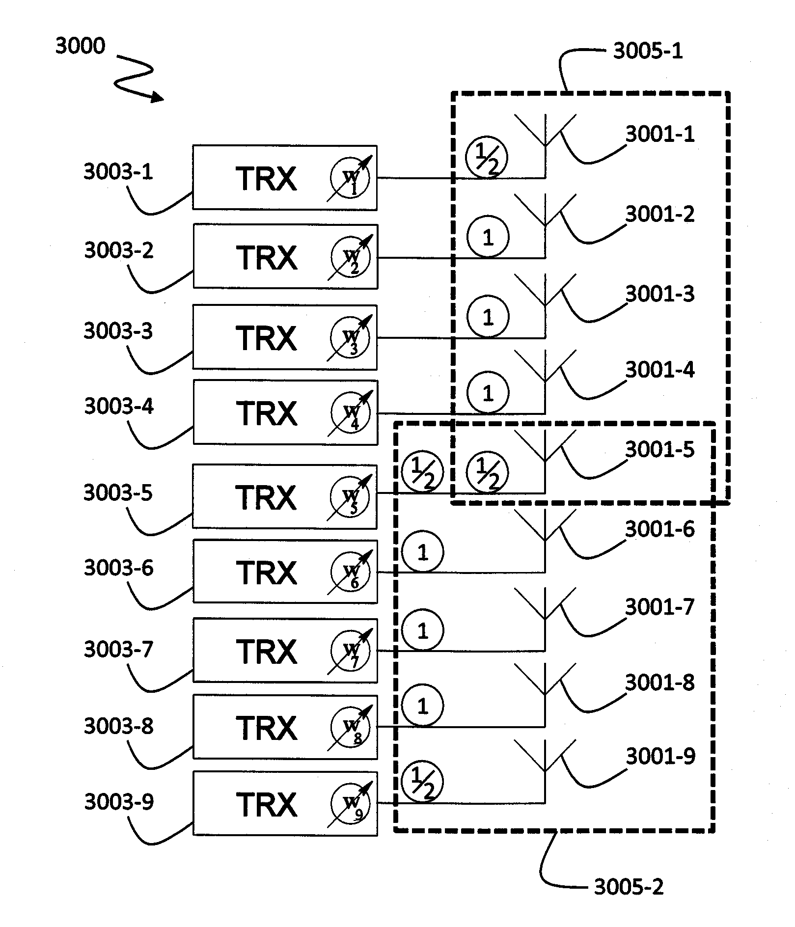
The skilled person will appreciate further that it would be possible to include two common antenna elements in one subset, but this would lead to a loss of flexibility.

Method used


Image

  • Antenna array and method for operating antenna array
  • Antenna array and method for operating antenna array
  • Antenna array and method for operating antenna array

Examples


Embodiment Construction

[0025]The invention will now be described on the basis of the drawings. It will be understood that the embodiments and aspects of the invention described herein are only examples and do not limit the protective scope of the claims in any way. The invention is defined by the claims and their equivalents. It will be understood that features of one aspect or embodiment of the invention can be combined with a feature of a different aspect or aspects and / or embodiments of the invention.

[0026]The term “base transceiver station (BTS)” in the context of this disclosure includes, but is not limited to, base stations, as known from GSM networks, as well as a node B (known from UMTS / 3G networks) or enhanced node B, and similar units used in other mobile communication network.

[0027]FIG. 3 shows an active antenna array 3000 according to a first aspect of the present disclosure. The antenna array 3000 comprises a plurality of antenna elements 3001-1 through 3001-9 arranged in a vertical column. I...


PUM


Abstract

The present invention refers to an active antenna array having a plurality of antenna elements comprising: at least one first subset of the plurality of antenna elements, the at least one first subset relaying a first radio signal having a first antenna beam pattern; and at least one second subset of the plurality of antenna elements, the at least one second subset relaying a second radio signal having a second antenna beam pattern, wherein at least one of the plurality of antenna elements is a common antenna element belonging to both the first subset and the second subset. A method for operating the active antenna array is also disclosed.

Description

CROSS-REFERENCE TO RELATED APPLICATION[0001]NoneFIELD OF THE INVENTION[0002]The field of the invention relates to an antenna array and a method for operating such an antenna array.BACKGROUND OF THE INVENTION[0003]The use of mobile communications networks has increased over the last decade. Operators of the mobile communications networks have increased the number of base transceiver stations in order to meet an increased demand for service by users of the mobile communications networks. The operators of the mobile communications network wish to reduce the running costs of the base transceiver station.[0004]Nowadays active antenna arrays are used in the field of mobile communications systems in order to reduce power transmitted to a handset of a customer and thereby increase the efficiency of the base transceiver station, i.e. the radio station. The radio station typically comprises a plurality of antenna elements, i.e. an antenna array adapted for transceiving a payload signal. Typic...

Claims


Application Information

Patent Timeline
Patent Type & Authority Applications(United States)
IPC IPC(8): H01Q3/00
CPCH01Q1/246H01Q25/00H01Q21/06H01Q3/28
Inventor SCHMIDT, GEORGEWECKERLE, MARTIN
Owner TELEFON AB LM ERICSSON (PUBL)
Learn More