Backpack frame

a frame and backpack technology, applied in the field of backpacks, can solve the problems of not supporting the oft considerable weight carried, not adequately stabilizing the load, and often carrying additional gear by soldiers, etc., to achieve the effect of optimizing load centering and stability

Active Publication Date: 2012-08-09
HERE BE DRAGONS LLC
View PDF12 Cites 3 Cited by
  • Summary
  • Abstract
  • Description
  • Claims
  • Application Information

AI Technical Summary

Benefits of technology

[0013]In both embodiments, the front panel is suspended between the frame arms inserted in the sleeves. Thus suspended, the front panel can flex inwardly and outwardly, as needed, to create space for the wearer's back-borne equipment. Front panel flexure thus optimizes load centering and stability on the ever changing convex surface of the wearer's back.

Problems solved by technology

The difficulty is that soldiers often need to carry additional gear (such as ammunition, radios, batteries, etc.) into battle as well.
These designs do not adequately support the oft considerable weight carried in this fashion, and they do not stabilize these loads adequately during the rigors of combat.
The loads primarily carried, ammunition and the like, are very dense.
Even a relatively small payload volume presents serious challenges to wearer comfort and balance.
While running, climbing, crawling, etc., the load will tend to shift, thus compromising balance during critical moments.
This problem is exacerbated when a hydration reservoir is worn on top of the armor plate and under the backpack.
This carriage position is inefficient and uncomfortable.
Prior art backpacks that use support sheets or full-frame support systems are even more prone to this than fabric / strap designs.
This forces the backpack away from the wearer's center of mass and causes the load to teeter on the equipment-formed pinnacle.

Method used


Image

  • Backpack frame
  • Backpack frame
  • Backpack frame

Examples


Embodiment Construction

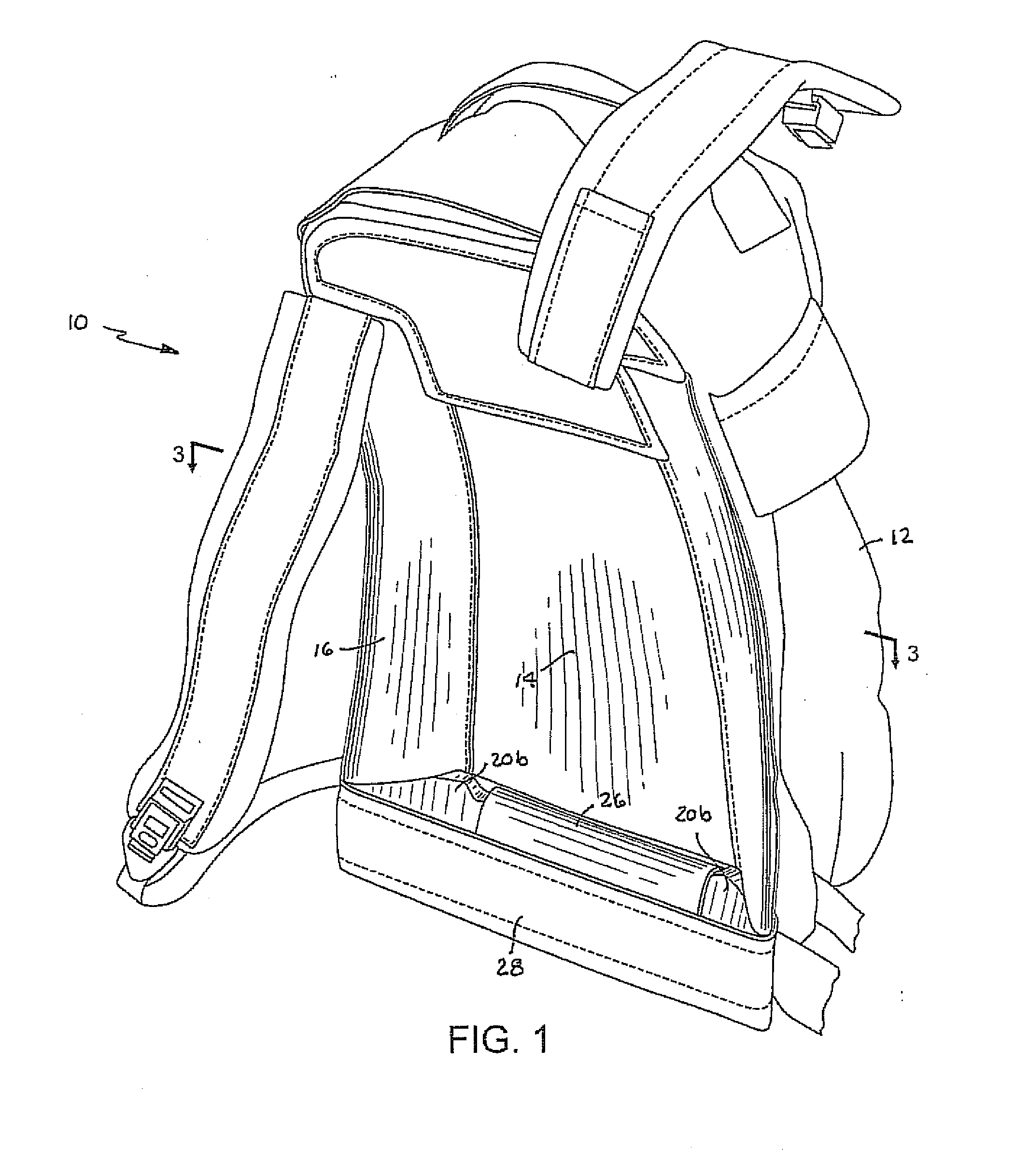
[0027]With reference initially to FIGS. 1-3, a backpack is generally depicted at 10.

[0028]The backpack includes a load carrying section 12 having a forwardly facing flexible front panel 14. The load carrying section is comprised principally of a fabric, with the stiffness of the front panel preferably being greater than the stiffness of the fabric. As shown in FIG. 3, the front panel can be stiffened by an additional sheet 15 adhered or otherwise integrally joined to its interior surface. Sheet 15 may comprise a foam or other rubber-like material which provides a cushioning effect.

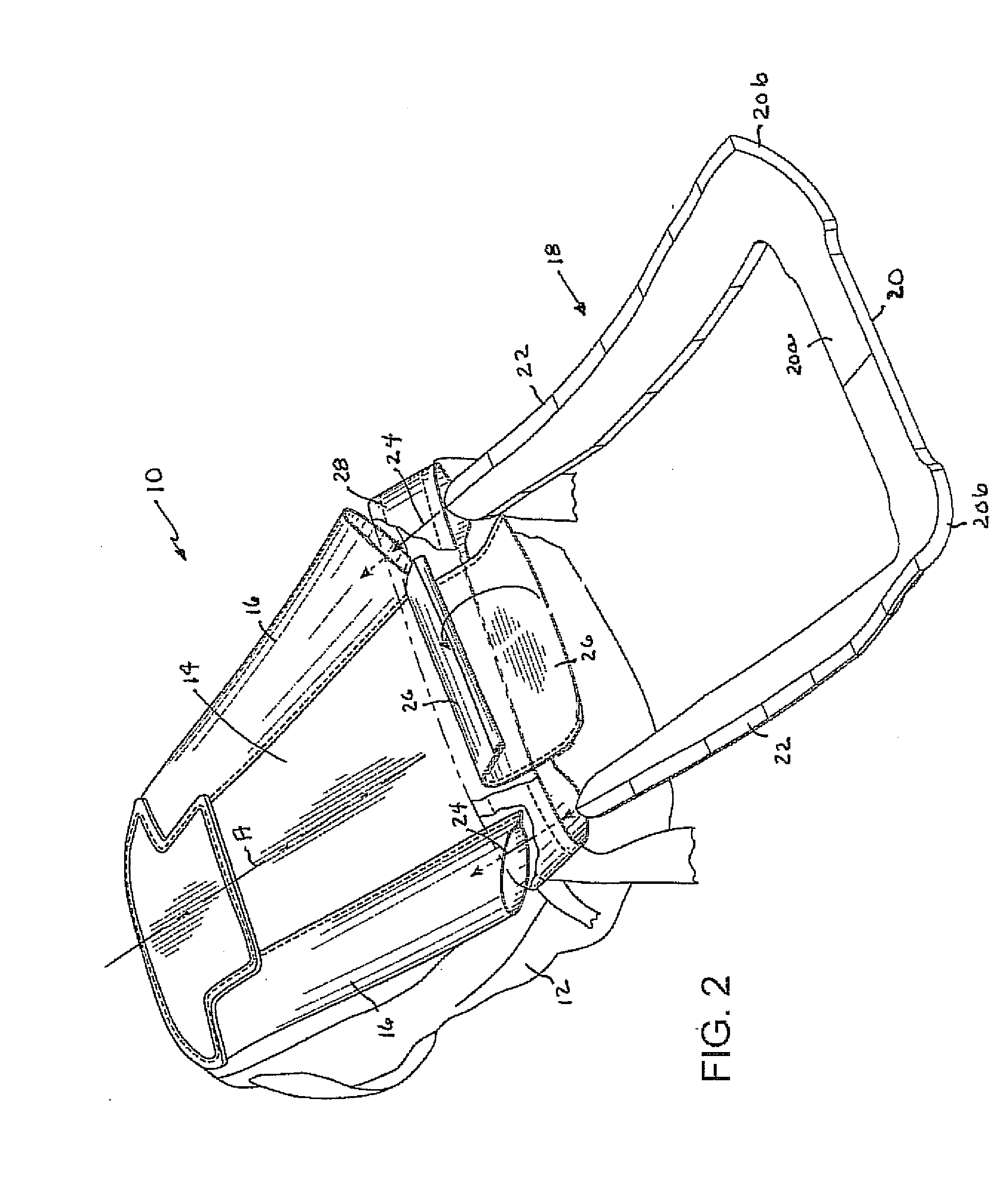
[0029]A pair of mutually spaced sleeves 16 are joined to and border the sides of the panel 14. As can best be seen in FIG. 2, the sleeves 16 are inclined laterally inwardly towards a central axis “A” of the backpack, and are closed at the top and open at the bottom.

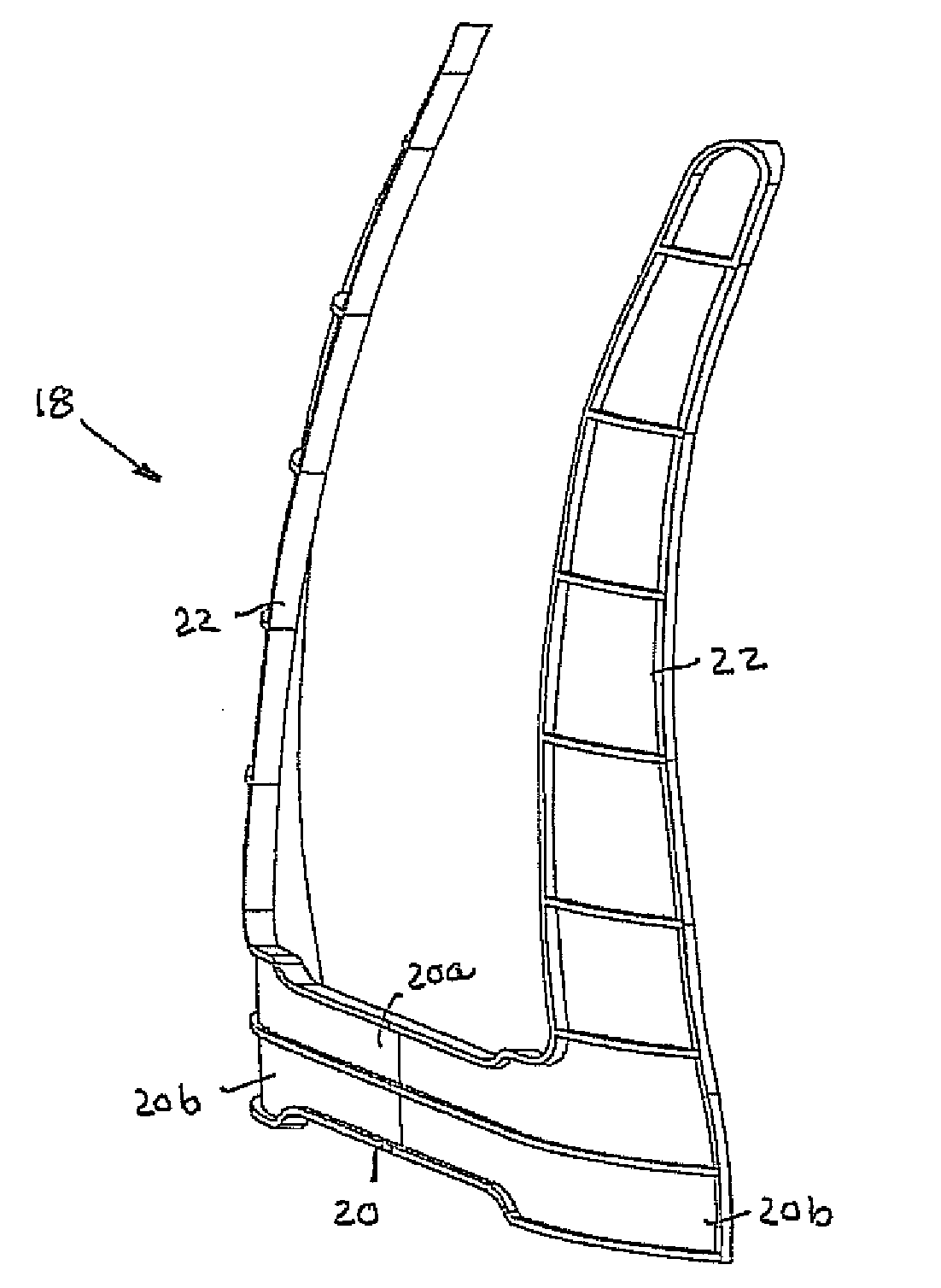
[0030]An injection molded partial perimeter generally U-shaped frame 18 in accordance with the present invention is assembled into the backpack...


PUM


Abstract

A backpack from has a forwardly facing side and a back side. The frame comprises a base having a generally flat midsection with forwardly curved end sections. A pair of mutually spaced arms project from the end sections of the base. The arms have a degree of twist that gradually diminishes from the end sections of the base to the upper distal ends of the arms.

Description

CROSS REFERENCE TO RELATED APPLICATIONS[0001]This application is a divisional of application Ser. No. 12 / 477,362 filed on Jun. 3, 2009.BACKGROUND[0002]1. Field of the Invention[0003]This invention relates generally to backpacks, and is concerned in particular with an internal injection molded partial-perimeter frame for insertion in backpacks formed principally of fabric.[0004]2. Description of Related Art[0005]Although the frame of the present invention is useful in a wide range of applications, its design is particularly suited for use in backpacks of military combat personnel.[0006]Soldiers engaged in combat must be able to carry gear while wearing bulky body armor vests and water reservoirs (commonly known as Camelbacks or hydration reservoirs). The preferred location for these items is on the wearer's back. The difficulty is that soldiers often need to carry additional gear (such as ammunition, radios, batteries, etc.) into battle as well. The preferred location for this gear i...

Claims


Application Information

Patent Timeline
Patent Type & Authority Applications(United States)
IPC IPC(8): A45F3/08A45F3/06
CPCA45F3/04A45F3/08A45F3/06
Inventor HOWELL, FRANK A.
Owner HERE BE DRAGONS LLC
Why Eureka
Try Eureka