
Fluorescent light emission enhancer light-cone

Inactive Publication Date: 2012-08-09
SAFAR SAMIR HANNA
View PDF3 Cites 0 Cited by
  • Summary
  • Abstract
  • Description
  • Claims
  • Application Information

AI Technical Summary

Benefits of technology

[0037]The foremost object of the present invention is to provide a novel light-cone that can enhance the emission of fluorescent light from a light bulb.
[0038]Another object of the present invention is to provide a light-cone light enhancer that can be made relatively easily and inexpensively.
[0039]Another object of the present invention is to provide a light-cone light enhancer which can be conveniently used in an unobtrusive manner with a fluorescent tube or bulb.
[0040]Another object of the present invention is to provide a light-cone light enhancer that reduces misdirected and absorbed light.
[0041]A further object of the present invention is to provide a light-cone light enhancer that eliminates unnecessary heat during the light enhancing process.

Problems solved by technology

This type of light is that the light emitted by the bulbs is often misdirected so that it never reaches the area where the illumination is desired.
Again use of more artificial illumination than required is expensive and energy-intensive.
Over-illumination can contribute to light pollution, where stray light illuminates the outdoors or others' property, where it is unwanted.
However, the problems posed by such reflectors or enhancers known in the field are many because of several factors such as the specific geometry of the reflector body, the reflectivity of the surface of the reflectors or enhancers, ability to withstand high temperatures, costs, finishes used on the reflector surface, etc.
For example reflectors or enhancers usually employ translucent covers beneath the fluorescent tubes or bulbs to diffuse the light evenly over the area of illumination; these translucent covers absorb light, thereby hampering efficiency
Again daily users of the fluorescent tube or bulb often find it difficult in procuring a ready to fit customized light reflector or enhancer.
Some cannot adequately reflect the light rays emitted at high angles permitting it to exceed the lateral boundaries of the area to be lighted.
Again typical reflectors or enhancers for fluorescent tube or bulb tend to concentrate light output in a downward direction (i.e. toward the floor) and do not provide a sufficiently desirable diffuse lighting characteristic (e.g. towards sidewalls, etc.).
Substantial amounts of light and energy are wasted by the reflector or enhancer due to light being directed toward areas, such as ceilings, where the light is not needed or desired.
Others tend to concentrate the light to a particular section of the area, reducing the apparent uniformity of illumination of such area, thus causes glare.
The misdirected light wastes electrical energy and leads to the undesired heating of the light fixture components.
Thus users usually resort to a made-to-order light reflectors or enhancers which results in more expenditure.
Again reflective components typically emit an undesired amount of infrared light along with the desired visible light.
In many instances, the components of the fluorescent tube or bulb or the reflector or enhancer become damaged by the excessive heat, and therefore must be replaced.
This results in an increased amount of misdirected light.
However the purpose and methodology of all the above inventions that are part of prior art do not envisage the unique embodiment of a light enhancer that is highly efficient, inexpensive, very convenient to use and made of noninflammable and heat resistant material.

Method used


Image

  • Fluorescent light emission enhancer light-cone
  • Fluorescent light emission enhancer light-cone
  • Fluorescent light emission enhancer light-cone

Examples


Embodiment Construction

[0046]The following description is presented to enable any person skilled in the art to make and use the invention, and is provided in the context of particular applications of the invention and their requirements. The present invention can be configured as follows:

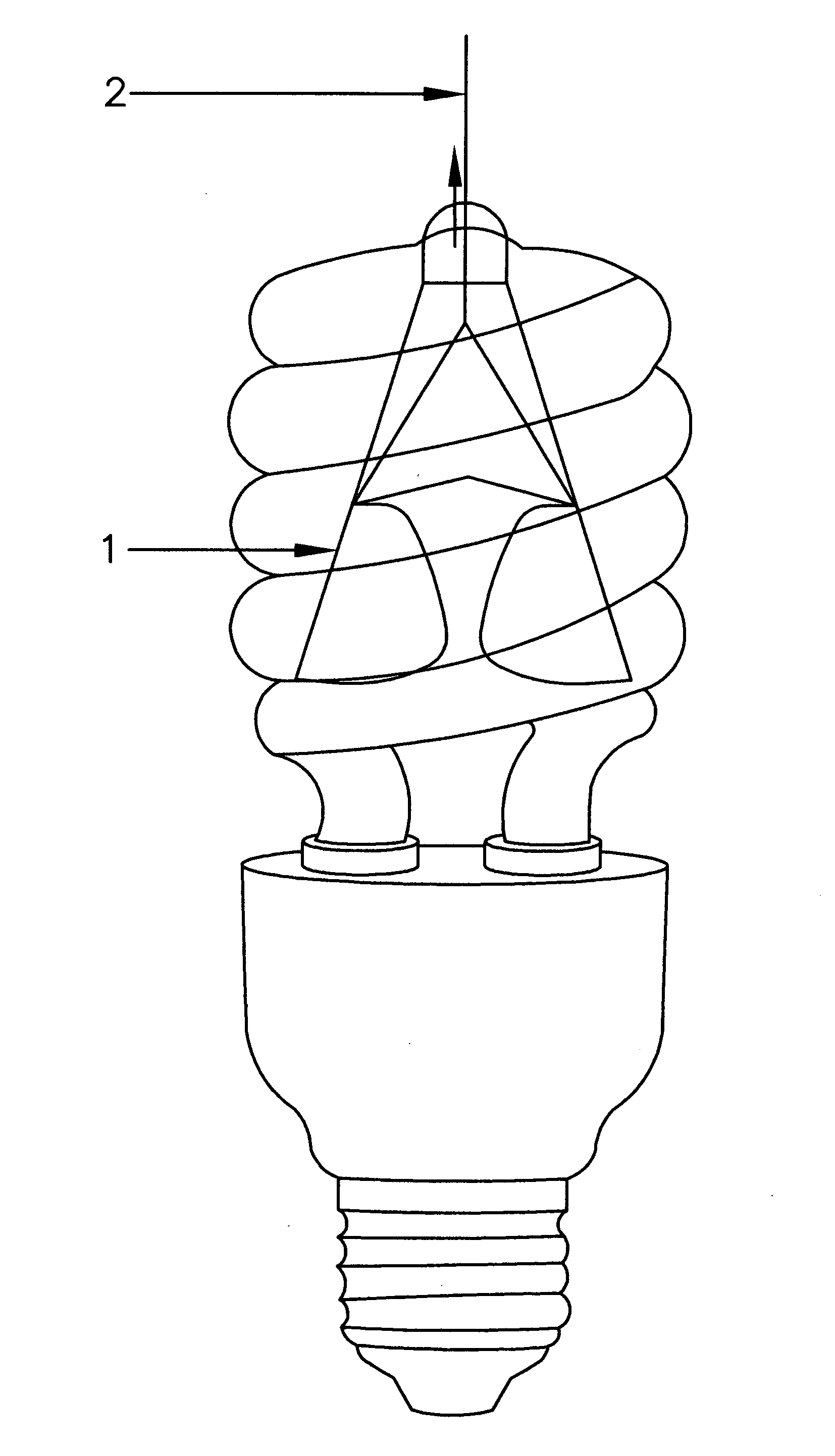
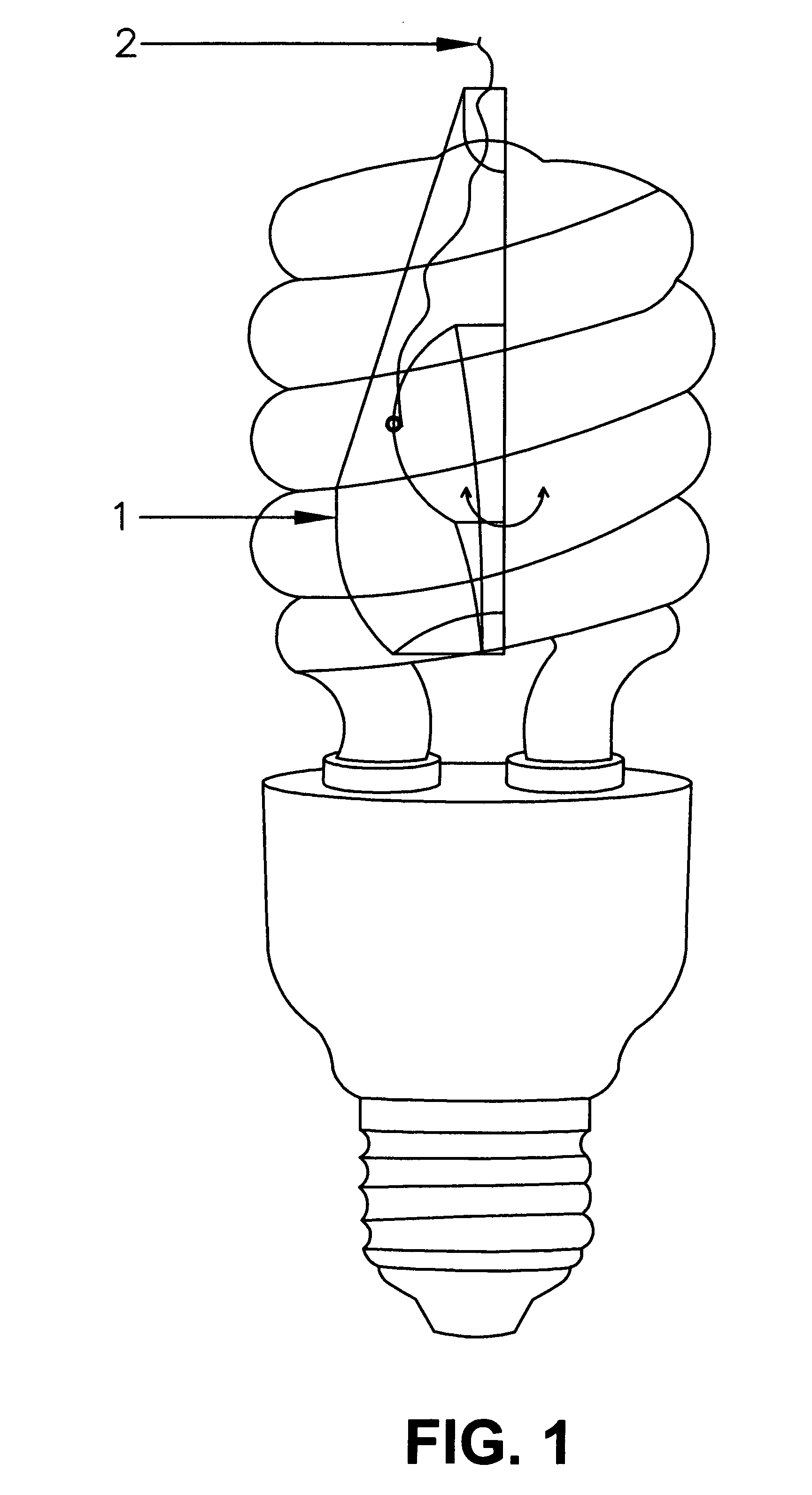
[0047]As detailed in FIG. 1, the present invention is a light-cone (1) that is flat and can be shaped into a conical configuration. The light-cone (1) is preferably made of non-flammable material and a high reflective surface material on the outside of the light-cone (1) including but not limited to aluminum.

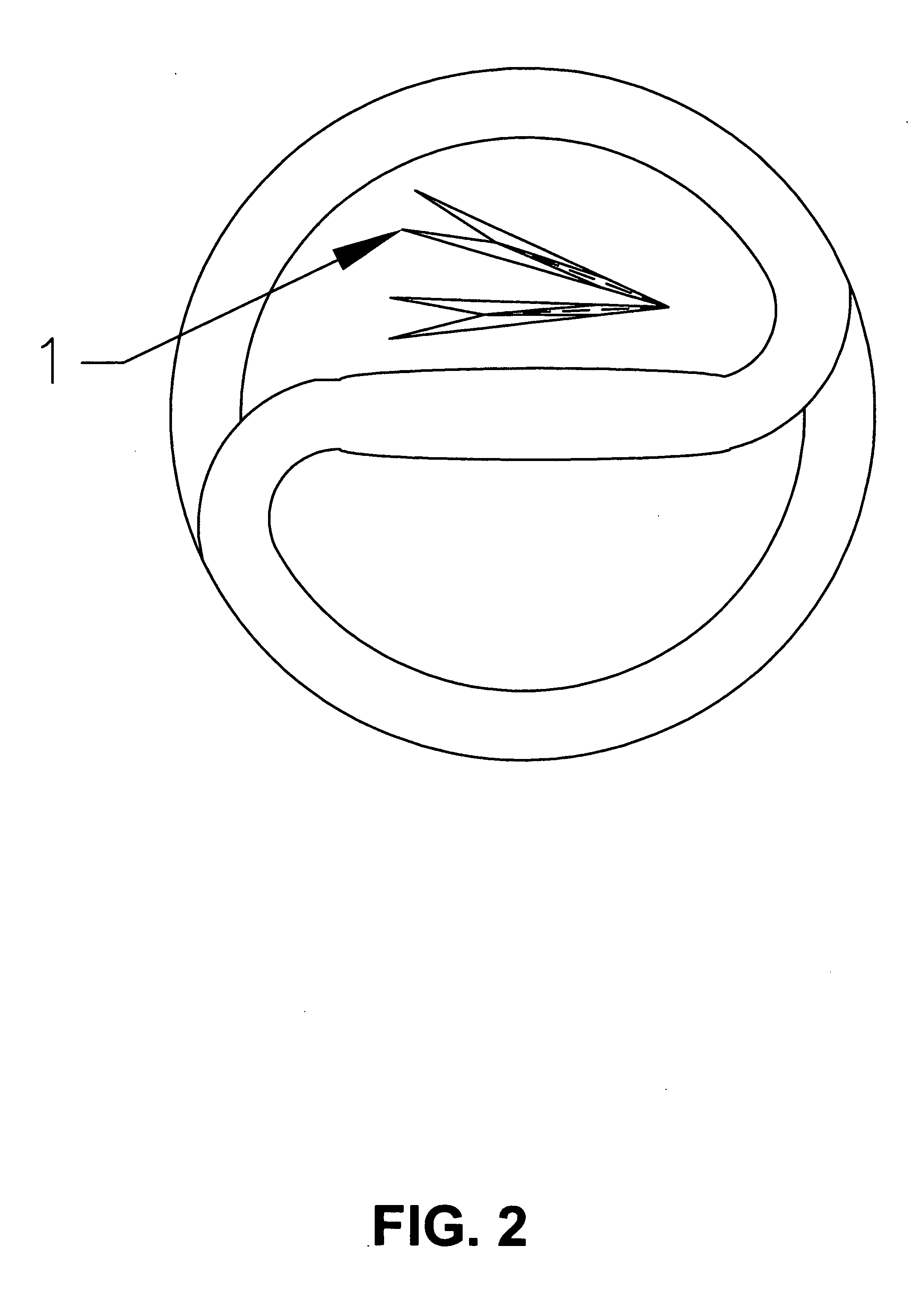
[0048]In a preferred embodiment of the present invention, as illustrated in FIGS. 1 and 2 a flat square or rectangular or triangular or circular piece of material is manually folded for insertion into the central aperture of the fluorescent light bulb. The light-cone (1) can be the shape of the funnel too. The present invention is thus designed to be placed inside a light fluorescent bulb.

[0049]In a preferred embodime...


PUM


Abstract

A fluorescent light emission enhancer light-cone for insertion into the central aperture of the fluorescent light bulb and subsequent expansion into a cone which helps increases the light intensity of said fluorescent light bulb by emitting outside almost half of light emission from said fluorescent light bulb that is lost inside between its loped tubes.

Description

FIELD OF THE INVENTION[0001]The present invention relates to the field of illumination devices, particularly to an illumination enhancer. More particularly the present invention relates to a novel light-cone that is designed to be placed inside a light fluorescent bulb and can substantially enhance the emission of fluorescent light.BACKGROUND OF THE INVENTION[0002]Fluorescent lighting is now in common use in homes, offices, hallways, stairways and public areas for providing illumination. A fluorescent lamp converts electrical power into useful light more efficiently than an incandescent lamp. Lower energy cost typically offsets the higher initial cost of the lamp.[0003]While larger fluorescent lamps have been mostly used in commercial or institutional buildings, the compact fluorescent lamp is now available in the same popular sizes as incandescents and is used as an energy-saving alternative in homes. These lights can be operated at greatly reduced costs when compared to incandesce...

Claims


Application Information

Patent Timeline
IPC IPC(8): F21V9/16
CPCF21V7/18F21V7/041H01J61/327H01J61/025
Inventor SAFAR, SAMIR HANNA
Owner SAFAR SAMIR HANNA
Learn More