
Organic electroluminescence device

Active Publication Date: 2014-02-06
IDEMITSU KOSAN CO LTD
View PDF1 Cites 9 Cited by
  • Summary
  • Abstract
  • Description
  • Claims
  • Application Information

AI Technical Summary

Benefits of technology

[0013]It is apparent from the above-mentioned prior art inventions, a technology in which emission is enhanced by about 1.5 times by introducing an organic layer having a thickness of several nm to 200 nm on an electrode, and at the same time, good chromaticity is exhibited, has not yet been disclosed.
[0014]In the field of a display panel or an illumination panel for a large-sized TV or the like for which low power consumption is desired, further

Problems solved by technology

The technology disclosed in Patent Document 2 has a problem that the ClEy value could not be decreased in order to obtain good blue emission, and as a result, color reproducibility as an RGB image display apparatus cannot be obtained.
Howev

Method used


Image

  • Organic electroluminescence device
  • Organic electroluminescence device
  • Organic electroluminescence device

Examples


Example

Synthesis Example 1 (Synthesis of Intermediate 1)

[0165]17.7 g of 9-phenylcarbazole, 6.03 g of potassium iodide, 7.78 g of potassium iodate, 5.90 mL of sulfuric acid and 50 mL of ethanol were put, and the resulting mixture was reacted at 75° C. for 2 hours.

[0166]After cooling, water and ethyl acetate were added, and the mixture was separated and extracted. The organic layer was washed with sodium bicarbonate water and water, and concentrated. The resulting crude product was purified by silica gel chromatography (toluene), and resulting solids were dried under reduced pressure, whereby 21.8 g of white solids were obtained. By the FD-MS analysis, the solids were identified as the intermediate 1.

Example

Synthesis Example 2 (Synthesis of Intermediate 2)

[0167]Under the stream of argon, dehydrated toluene and dehydrated ether were added to 13.1 g of intermediate 1. The resultant was cooled to −45° C. Then, 25 mL of an n-butyllithium hexane solution (1.58M) was added dropwise, and the resulting mixture was heated to −5° C. for 1 hour with stirring. Again, the mixture was cooled to −45° C., and 25 mL of boronic acid triisopropyl ester was gradually added dropwise, and the mixture was allowed to react for 2 hours.

[0168]After heating to room temperature, a 10% dilute hydrochloric acid solution was added to the mixture, followed by stirring, whereby an organic layer was extracted. After washing with saturated saline, the organic layer was dried with anhydrous magnesium sulfate, filtrated, and then concentrated. The resulting solids were purified by silica gel chromatography (toluene). The resulting solids were washed with n-hexane, and then dried under reduced pressure, whereby 7.10 g of s...

Example

Synthesis Example 3 (Synthesis of Intermediate 3)

[0169]Under the atmosphere of argon, 100 mL of toluene, 100 mL of 1,2-dimethoxyethane and 50 ml of a 2M aqueous sodium carbonate solution were added to 32.5 g of 3,6-dibromocarbazole, 63.2 g of intermediate 2, 0.92 g of tetrakis(triphenylphosphine)palladium (0). The resulting mixture was heated with reflux for 10 hours.

[0170]After completion of the reaction, the mixture was immediately filtered, and then the aqueous phase was removed. After drying with sodium sulfate, the organic phase was concentrated. The residue was purified by silica gel chromatography, whereby 45.5 g of white crystals were obtained. By the FD-MS analysis, the crystals were identified as the intermediate 3.


PUM


Abstract

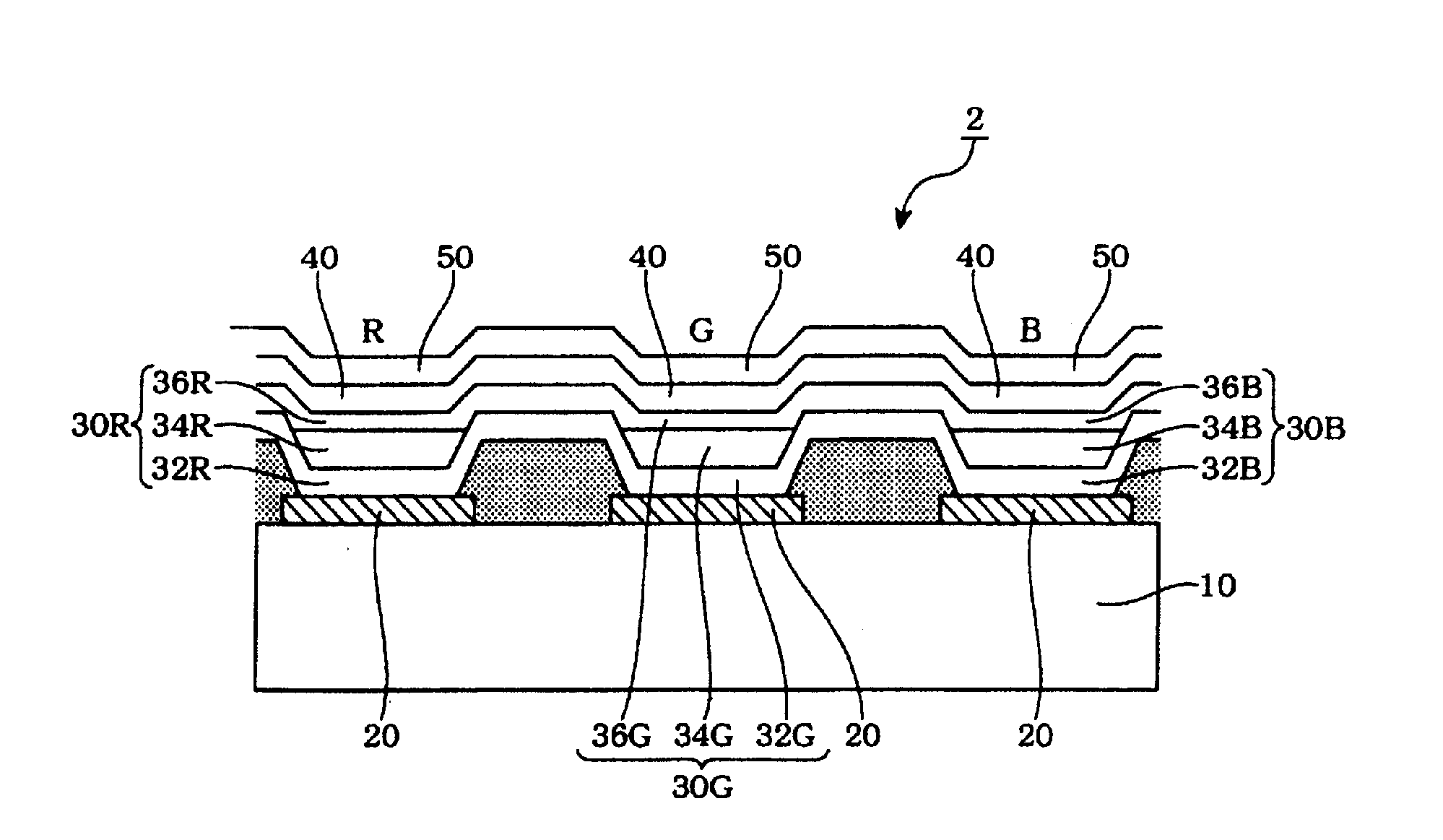
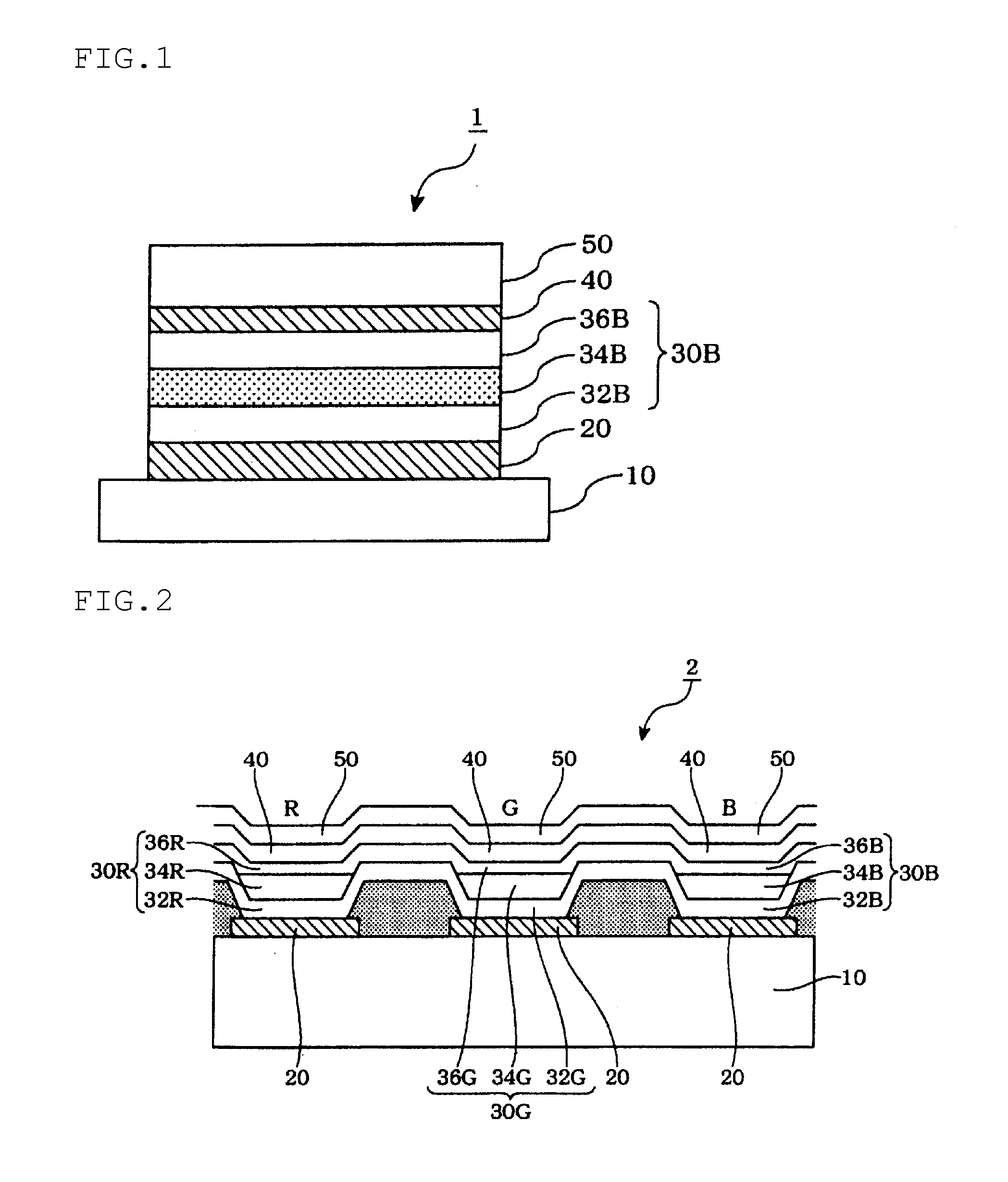
A top-emitting organic electroluminescence device including sequentially a first electrode, one or more organic layers comprising an emitting layer, a second electrode and a capping layer, wherein the capping layer comprises a compound represented by the following formula (1):

Description

TECHNICAL FIELD[0001]The invention relates to an organic electroluminescence (EL) device. In particular, the invention relates to an organic EL device which can be used in a display panel or an illumination panel for a large-sized TV, for which low consumption power is desired.BACKGROUND ART[0002]In order to improve luminous efficiency of an organic EL device, a technology of adjusting the optical interference distance is widely used. Further, in a top-emitting organic EL device, as means to improve the luminous efficiency, to allow the emission spectrum to be narrow and sharp and to adjust the peak wavelength, a technology of adjusting emission spectrum by disposing an organic layer including an emitting layer between a metal electrode and a semi-transparent metal electrode to configure an optical resonator has been widely used. By this technology, the length of a resonator is adjusted by changing the distance between the metal electrode and the semi-transparent electrode. A method...

Claims


Application Information

Patent Timeline
IPC IPC(8): H01L51/00
CPCH01L51/0071H10K85/6576H10K85/6574H10K85/6572H10K50/858H10K50/844H10K85/657H10K50/11
Inventor SAITO, HIROYUKINARAOKA, RYOKATO, TOMOKINUMATA, MASAKI
Owner IDEMITSU KOSAN CO LTD
Learn More