
Automotive headlamp forming multiple light distribution patterns with a single lamp

Active Publication Date: 2012-08-09
KOITO MFG CO LTD
View PDF15 Cites 24 Cited by
  • Summary
  • Abstract
  • Description
  • Claims
  • Application Information

AI Technical Summary

Benefits of technology

[0007]The present invention has been made in view of these situations, and a purpose of the invention is to provide an automotive headlamp that has a simple and low-cost structure and is capable of forming a plurality of light distribution patterns with a single lamp.

Problems solved by technology

Accordingly, there is the problem that the structure of the automotive headlamp becomes complicated and the cost is increased.

Method used


Image

  • Automotive headlamp forming multiple light distribution patterns with a single lamp
  • Automotive headlamp forming multiple light distribution patterns with a single lamp
  • Automotive headlamp forming multiple light distribution patterns with a single lamp

Examples


embodiment 1

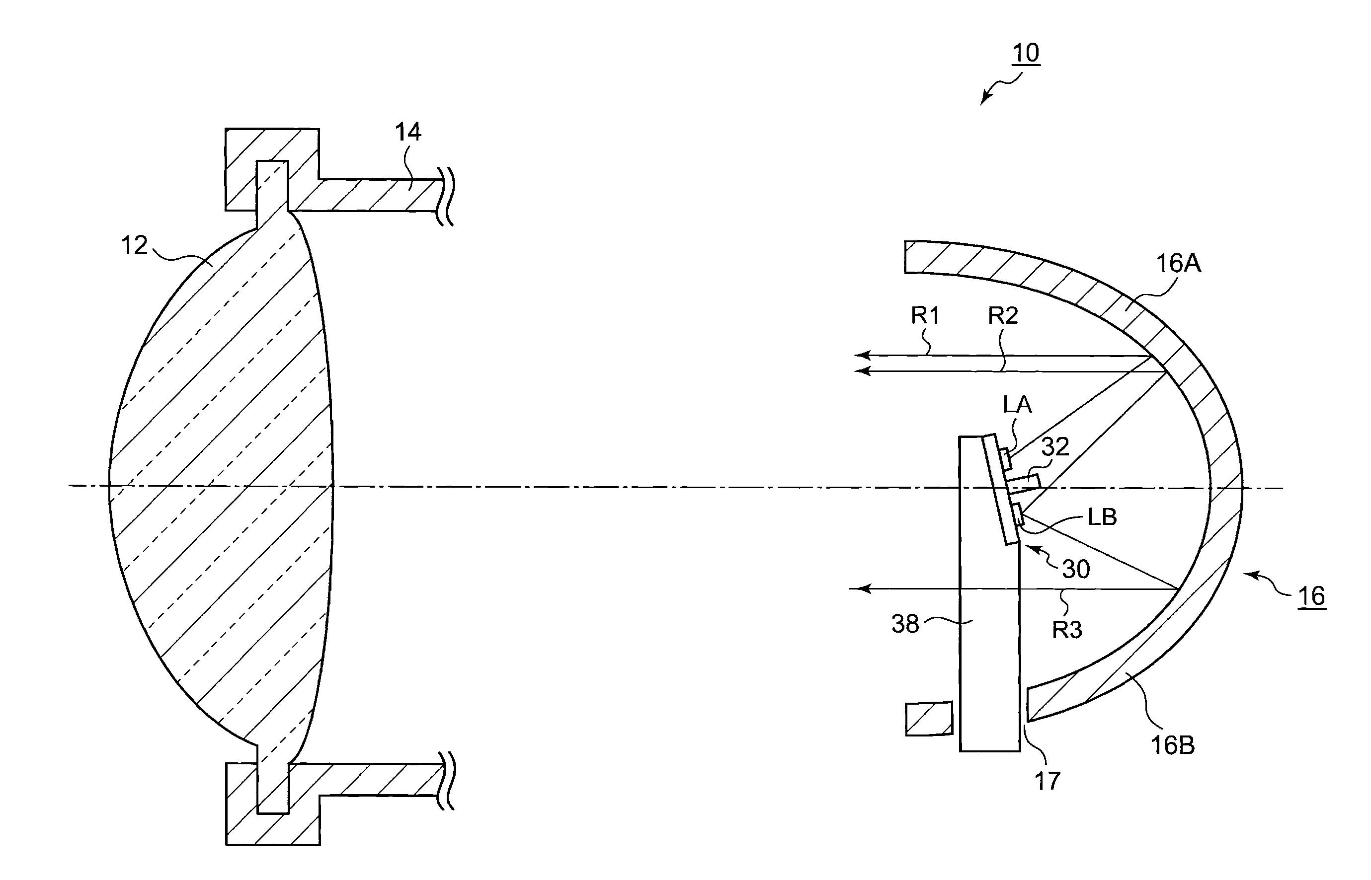
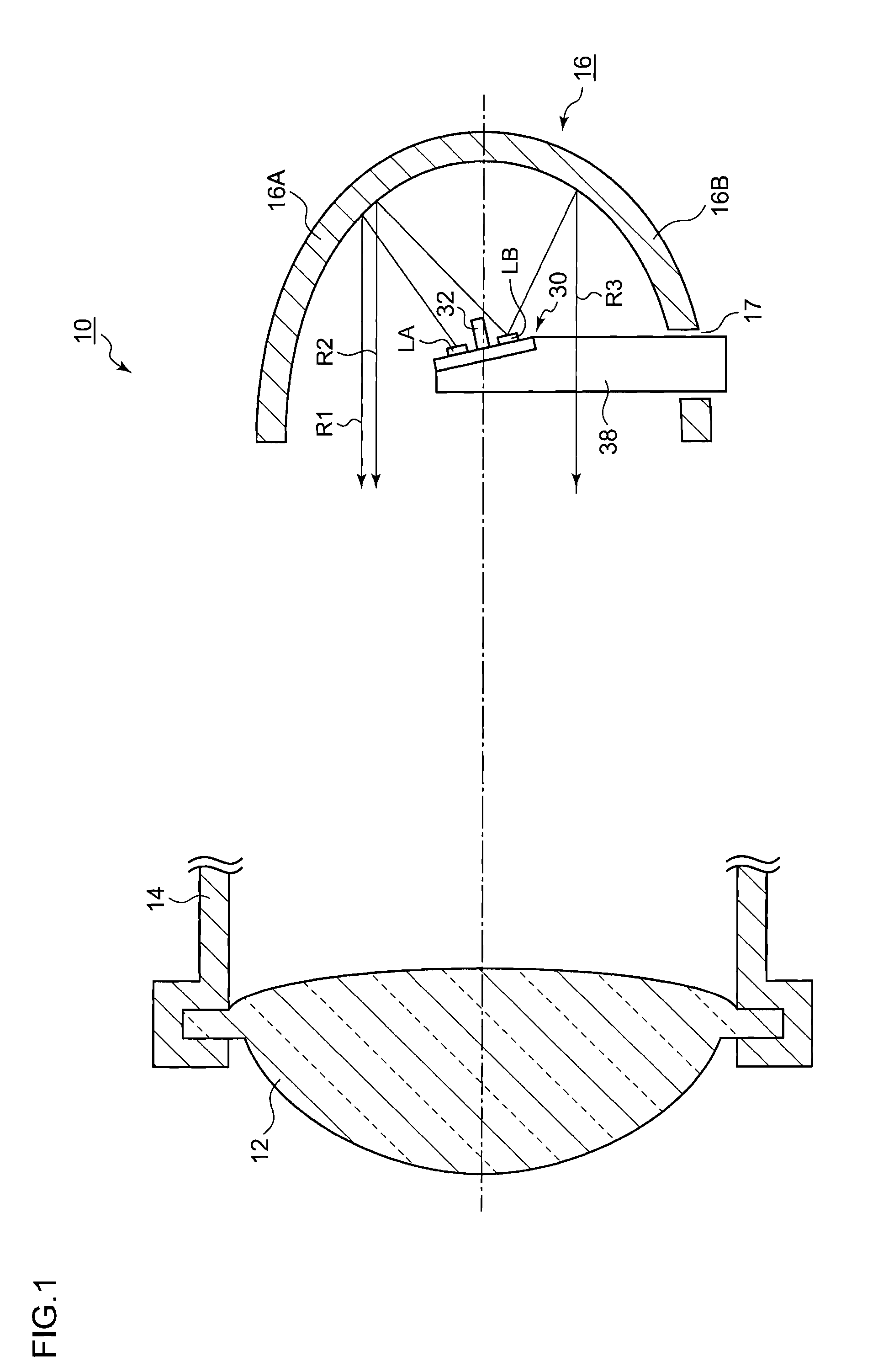
[0024]FIG. 1 is a schematic sectional view for explaining the internal structure of an automotive headlamp 10 according to Embodiment 1. FIG. 1 illustrates the section of the automotive headlamp 10 cut by the vertical plane including the central axis of a lamp. The automotive headlamp 10 according to the present embodiment is an automotive headlamp mainly used for two-wheeled vehicles, which emits light so as to form, with a single lamp, predetermined light distribution patterns in front of a vehicle.

[0025]The automotive headlamp 10 mainly has a projection lens 12, a lens support member 14, a reflector 16, and a light source portion 30.

[0026]The projection lens 12 is arranged on the central axis extending in the longitudinal direction of a vehicle, and is supported by the lens support member 14 so as to cover the front opening of the reflector 16. The projection lens 12 is composed of a plano-convex aspheric lens whose front surface is convex-shaped, and projects a light source imag...

embodiment 2

[0055]FIG. 6 is a schematic sectional view for explaining the internal structure of an automotive headlamp 40 according to Embodiment 2. The automotive headlamp 40 has the same configuration as that of the automotive headlamp 10 described in FIG. 1, except a light source portion 50.

[0056]In Embodiment 2, the light source portion 50 comprises a stepwise substrate 52 in order to arrange a first light source LA and a second light source LB at positions having different distances from a reflector 16. The first light source LA is arranged, with respect to the reflector 16, on the front side of a lamp, and the second light source LB is arranged, with respect to the reflector 16, on the protrusion side thereof. By configuring the substrate 52 so as to be stepwise, a shape is formed in which a step portion 54 extends in the lateral direction (right side in the view) of the first light source LA. Thereby, the step portion 54 also functions as a light-shielding plate for shielding the light e...


PUM


Abstract

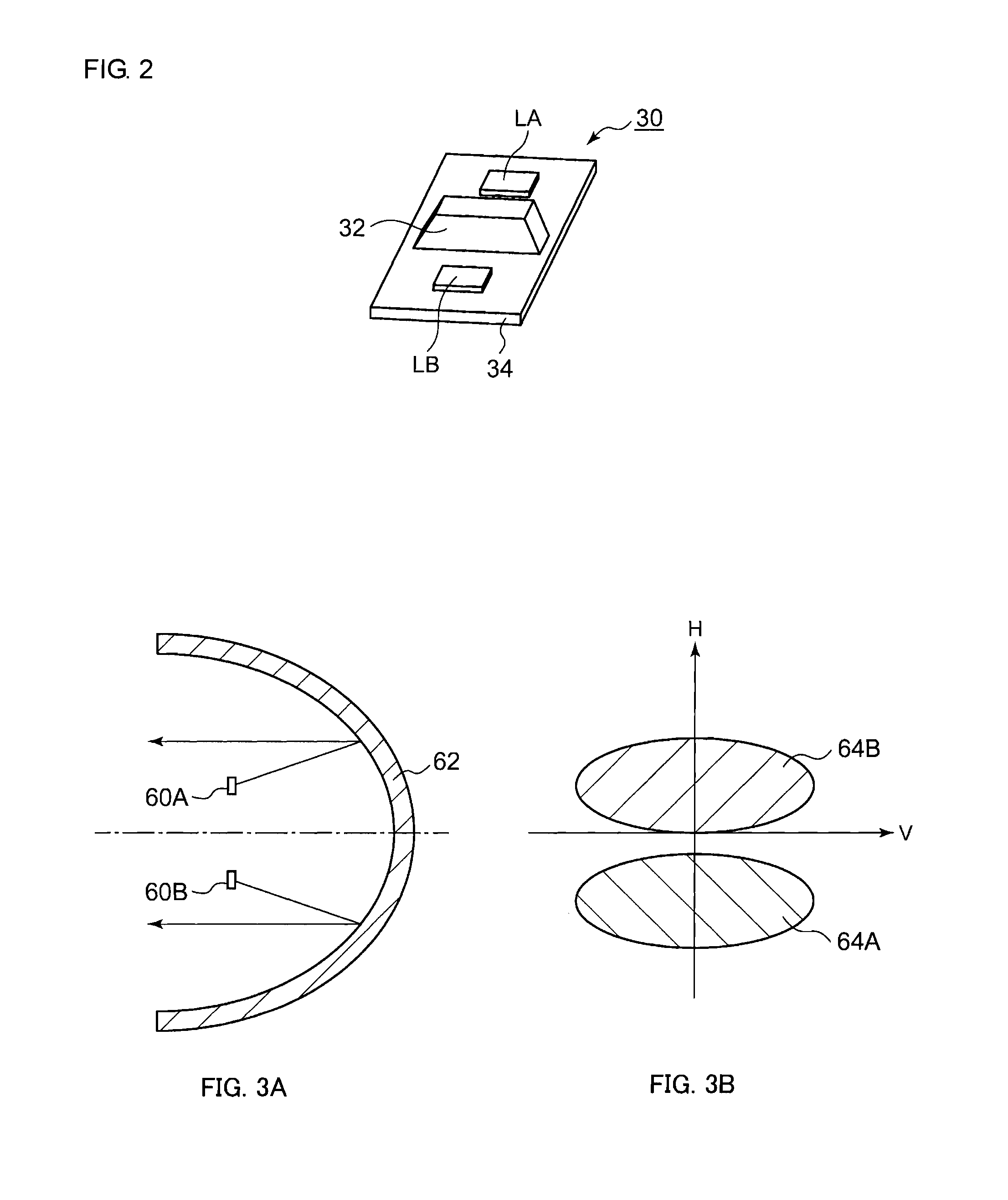
A reflector includes a first reflector portion located above the central axis of a headlamp extending in the longitudinal direction of a vehicle, and a second reflector portion located below the central axis. A first light source and a second light source are arranged such that: the light emitted from the first light source is reflected by the first reflector portion to form a first light distribution pattern; and the light emitted from the second light source forms two partial light distribution patterns by being reflected with both the first reflector portion and the second reflector portion, and a second light distribution pattern, which is different from the first light distribution pattern, is formed by combining the two partial light distribution patterns.

Description

BACKGROUND OF THE INVENTION[0001]1. Field of the Invention[0002]The present invention in general relates to an automotive headlamp forming a plurality of light distribution patterns with a single lamp.[0003]2. Description of the Related Art[0004]Automotive headlamps are generally configured to switch a low beam and a high beam. The low beam is used for lighting a near region with a predetermined illuminance, and light distribution of the low beam is specified so as not to provide glare to oncoming vehicles and leading vehicles. The low beam is mainly used while a vehicle is running in an urban area. On the other hand, the high beam is used for lighting a forward wide range and a far region with a relatively high illuminance. The high beam is mainly used while a vehicle is running at high speed on a road where oncoming vehicles and leading vehicles are few.[0005]In many cases, the automotive headlamps as described above are configured to select a plurality of light distribution patte...

Claims


Application Information

Patent Timeline
IPC IPC(8): B60Q1/00
CPCF21S48/1104F21S48/1747F21S48/1358F21S48/1159F21Y2107/50F21S41/19F21S41/147F21S41/334F21S41/43F21S41/663F21S41/145F21S41/151
Inventor NAGANAWA, MASAHITO
Owner KOITO MFG CO LTD
Learn More