Electronic device

a technology of electronic devices and housings, applied in the direction of transducer details, electrical transducers, electrical apparatus, etc., can solve the problems of reducing and achieve the effect of increasing the design freedom of housings

Inactive Publication Date: 2012-08-09
NEC CORP
View PDF7 Cites 26 Cited by
  • Summary
  • Abstract
  • Description
  • Claims
  • Application Information

AI Technical Summary

Benefits of technology

[0017]With the configurations as described above, the present invention can increase the freedom of design of a housing.

Problems solved by technology

Therefore, there is a problem that the freedom of design of the housing decreases.
Moreover, such a problem also occurs in a case that the first division space adjoining the front face of the diaphragm and the second division space adjoining the back face of the diaphragm are formed inside the housing.

Method used


Image

  • Electronic device
  • Electronic device
  • Electronic device

Examples


first exemplary embodiment

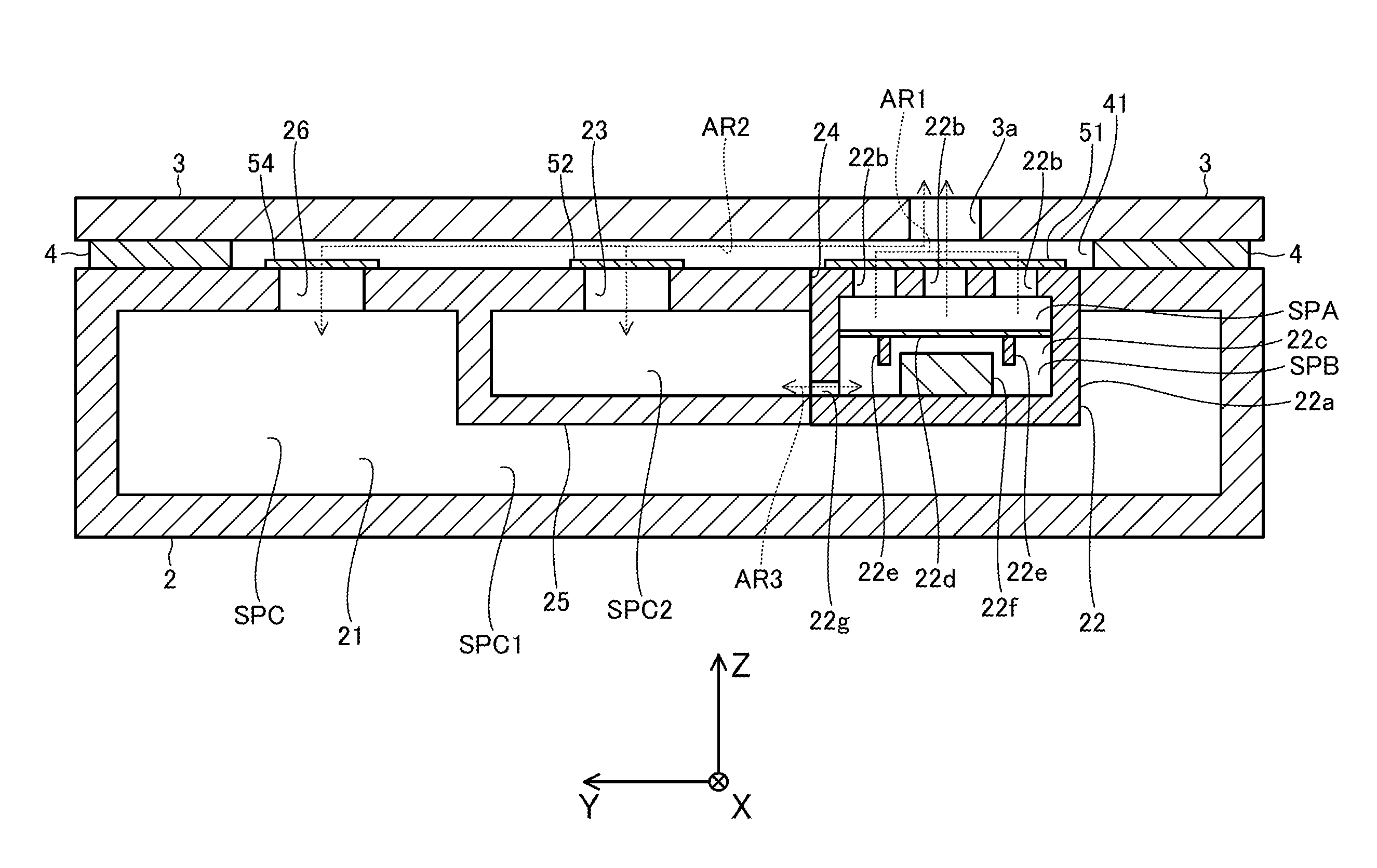
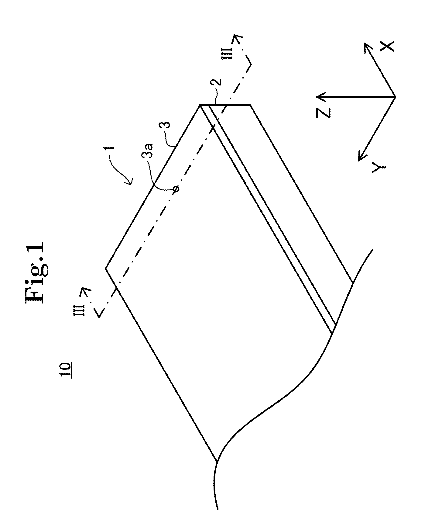
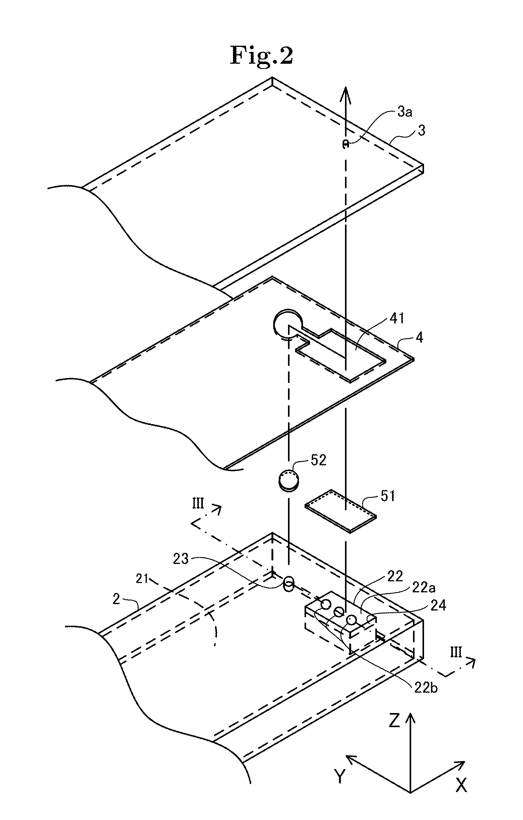
[0027]As shown in FIG. 1, an electronic device 10 according to a first exemplary embodiment is equipped with a housing 1. The housing 1 is formed like a rectangular parallelepiped. The housing 1 has a sealed structure. In this exemplary embodiment, the electronic device 10 is a mobile phone. The housing 1 includes a base part 2 and a surface part 3. Below, a description will be continued using the right-handed Cartesian coordinate system composed of the x-axis, the y-axis and the z-axes.

[0028]As shown in FIG. 1, the base part 2 is formed like a rectangular parallelepiped. The base part 2 configures a portion on the negative side in the z-axis direction of the housing 1. The surface part 3 is formed like a flat board. The surface part 3 configures a portion on the positive side in the z-axis direction of the housing 1. The surface part 3 is placed so as to be laminated on the base part 2 in the z-axis direction.

[0029]The surface part 3 is provided with a pierced hole 3a pierced in th...

second exemplary embodiment

[0064]Next, an electronic device according to a second exemplary embodiment of the present invention will be described. The electronic device according to the second exemplary embodiment is different from the electronic device according to the first exemplary embodiment in that the internal space 21 of the housing 1 is divided into three spaces. Therefore, a description will be made focusing on the different point.

[0065]The base part 2 in the second exemplary embodiment has a bulkhead 25 as shown in FIG. 5. The bulkhead 25 divides the remaining internal space SPC into a first remaining internal space SPC1 and a second remaining internal space SPC2. The second remaining internal space SPC2 adjoins the opening 22g and the first opening 23.

[0066]Further, the surface on the positive side in the z-axis direction of the base 2 is provided with a third opening 26 that opens to the outside of the base part 2, in addition to the first opening 23 and the second opening 24. The third opening 2...

third exemplary embodiment

[0080]Next, an electronic device according to a third exemplary embodiment of the present invention will be described. The electronic device according to the third exemplary embodiment is different from the electronic device according to the first exemplary embodiment in that the internal space 21 of the housing 1 is divided into three spaces, and in that an opening of the housing 1 adjoining a space adjoining the front face of the diaphragm 22d and an opening of the housing 1 adjoining a space adjoining the back face of the diaphragm 22d are different from each other. Therefore, a description will be made focusing on the difference point.

[0081]The base part 2 in the third exemplary embodiment has a bulkhead 27 as shown in FIG. 7. The bulkhead 27 divides the remaining internal space SPC into the first remaining internal space SPC1 and the second remaining internal space SPC2 on the y-axis. The first remaining internal space SPC1 adjoins the first opening 23.

[0082]Further, the surfac...


PUM


Abstract

An electronic device 100 includes a signal converter 110 and a housing 120. The signal converter has a diaphragm 111 and, when one of an acoustic signal and an electric signal is inputted, converts the inputted signal into the other signal by the vibrations of the diaphragm. The housing is provided with an internal space SPD. The housing holds the signal converter in the internal space. The housing is provided with an opening 121. The housing has a bulkhead 122 dividing the internal space into plural division spaces including a first division space SPD1 and a second division space SPD2. The diaphragm configures at least part of a bulkhead forming the first division space. The housing is provided with a first communicating path that makes the first division space communicate with the opening, and a second communicating path that makes the second division space communicate with the opening.

Description

TECHNICAL FIELD[0001]The present invention relates to an electronic device equipped with a signal converter converting one of an acoustic signal and an electric signal into the other.BACKGROUND ART[0002]There is a known electronic device equipped with a signal converter (a receiver, a speaker, or a microphone) having a diaphragm and, when one of an acoustic signal (an acoustic wave) and an electric signal is inputted, converting the inputted signal into the other signal by the vibrations of the diaphragm.[0003]As one of this type of electronic devices, an electronic device described in Patent Document 1 is equipped with a housing in which an internal space is formed. The internal space is divided into a plurality of division spaces including a first division space and a second division space. A signal converter is held in the first internal space.[0004]Further, the housing is provided with a plurality of openings that opens to the outside of the housing. In addition, the housing is ...

Claims


Application Information

Patent Timeline
Patent Type & Authority Applications(United States)
IPC IPC(8): H04R1/02H04M1/00
CPCH04M1/035H04R2499/11H04R1/021H04R1/083H04R1/086
Inventor SHIOGAMA, NAOKIOSAKO, TOMOFUMI
Owner NEC CORP
Why Eureka
Try Eureka