Pile installation and monitoring system and method of using the same

a monitoring system and installation technology, applied in the field of pile installation and monitoring system and method of using the same, can solve the problems of increasing the cost of installation, and wasting a lot of resources, so as to simplify the certification process of installed piles, improve installation information, and improve the effect of installation

Inactive Publication Date: 2012-08-09
PILE DYNAMICS
View PDF14 Cites 19 Cited by
  • Summary
  • Abstract
  • Description
  • Claims
  • Application Information

AI Technical Summary

Benefits of technology

[0006]The invention of this application relates to a monitoring system and, more particularly, to a monitoring system that can be utilized to vastly improve and streamline the pile installation process to both improve information concerning the installation and to simplify the certification process for the installed pile.
[0007]More particularly, the invention of this application relates to a device and a method for using the device that improves data entry, storage and usage relating to the installation of the pile.

Problems solved by technology

However, in view of the fact that a pile plays such a critical role in the overall integrity of a structure and is difficult or impossible to repair after the structure is completed, it is important to produce a structurally sound pile and to do so with a high degree of certainty.
As a result, while quality piles are being produced, they are often more expensive than necessary for the weight to be supported.
While some of these steps have been successful, there is still considerable waste and unnecessary over engineering in the industry.

Method used


Image

  • Pile installation and monitoring system and method of using the same
  • Pile installation and monitoring system and method of using the same
  • Pile installation and monitoring system and method of using the same

Examples


Embodiment Construction

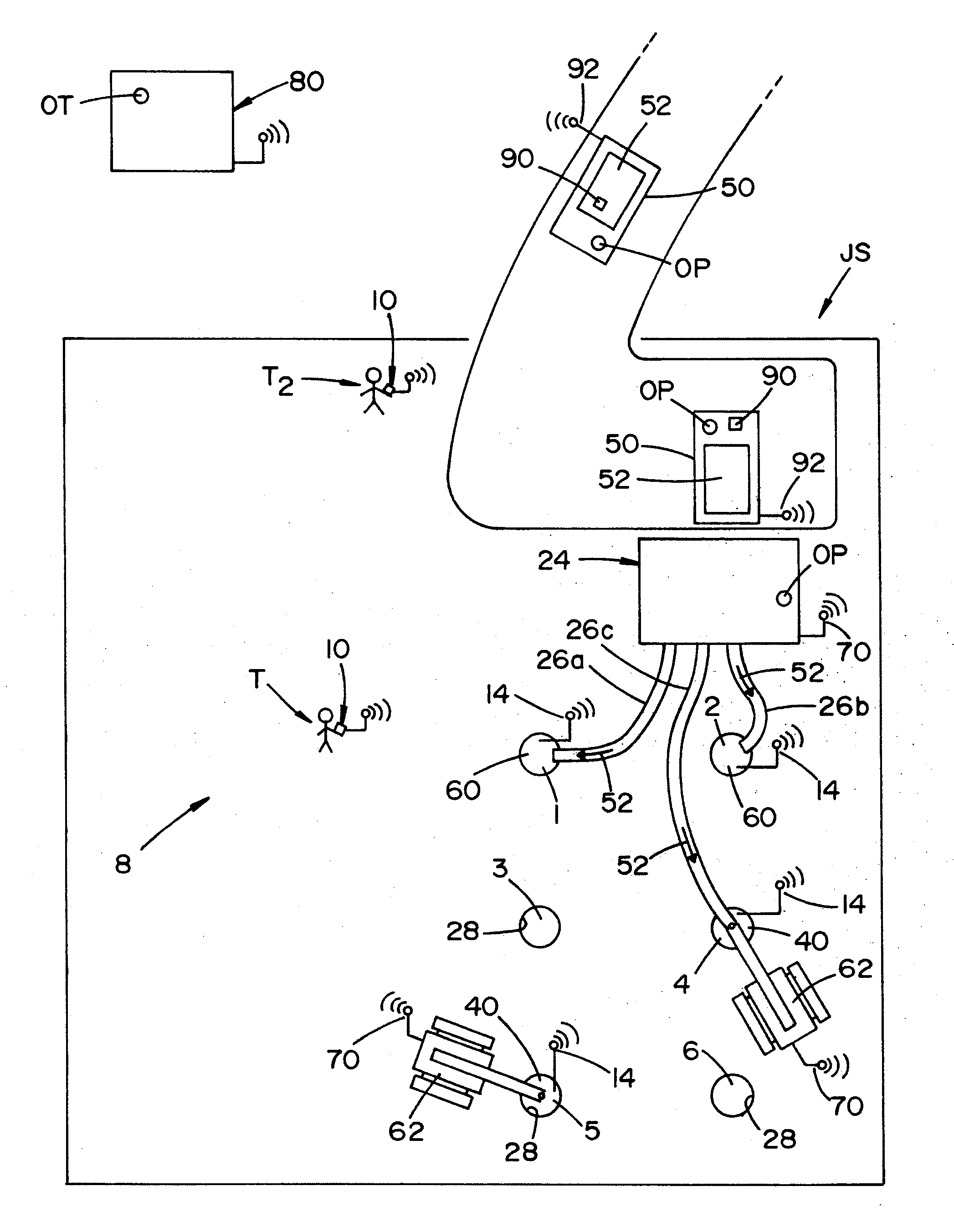
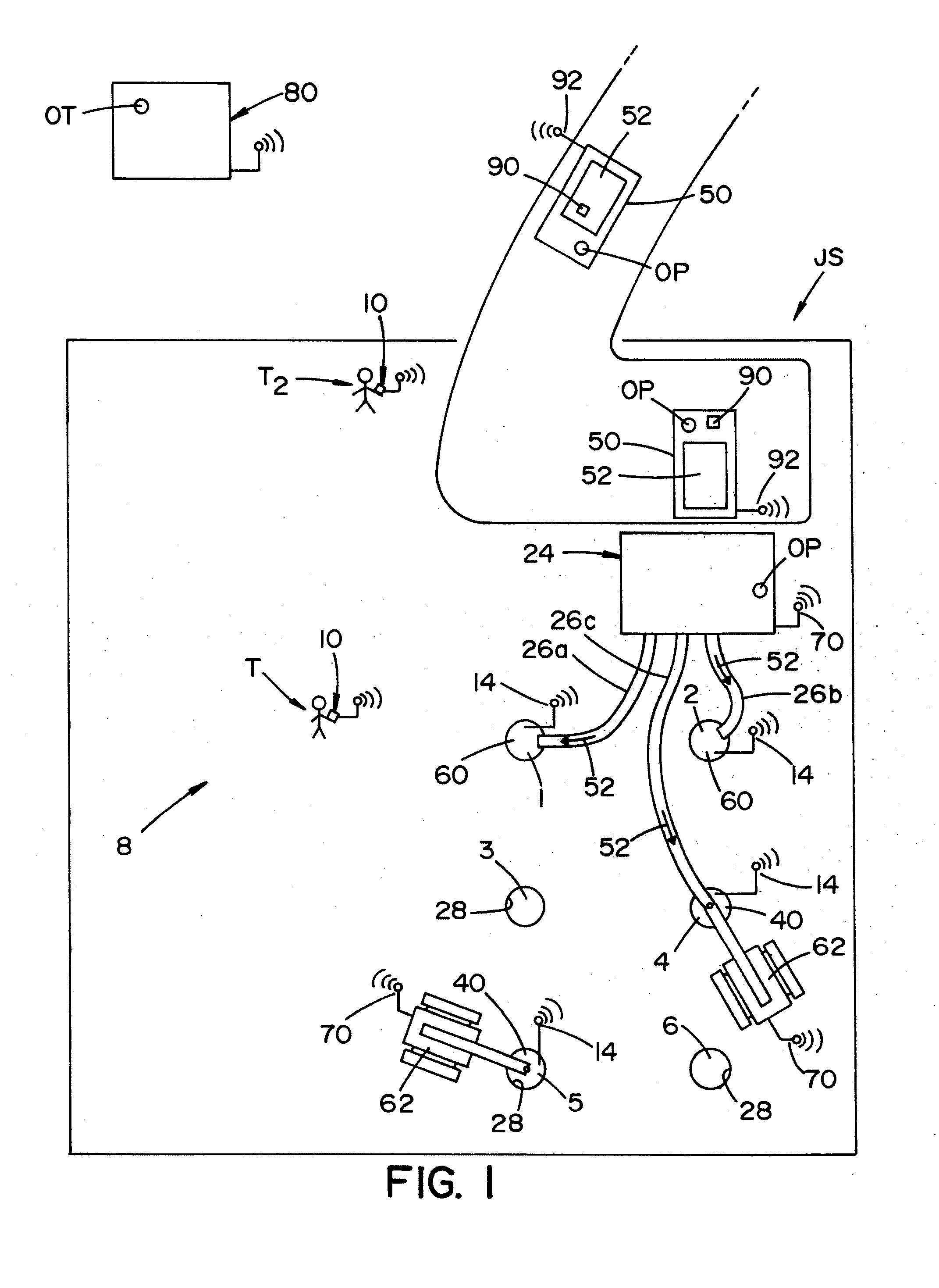
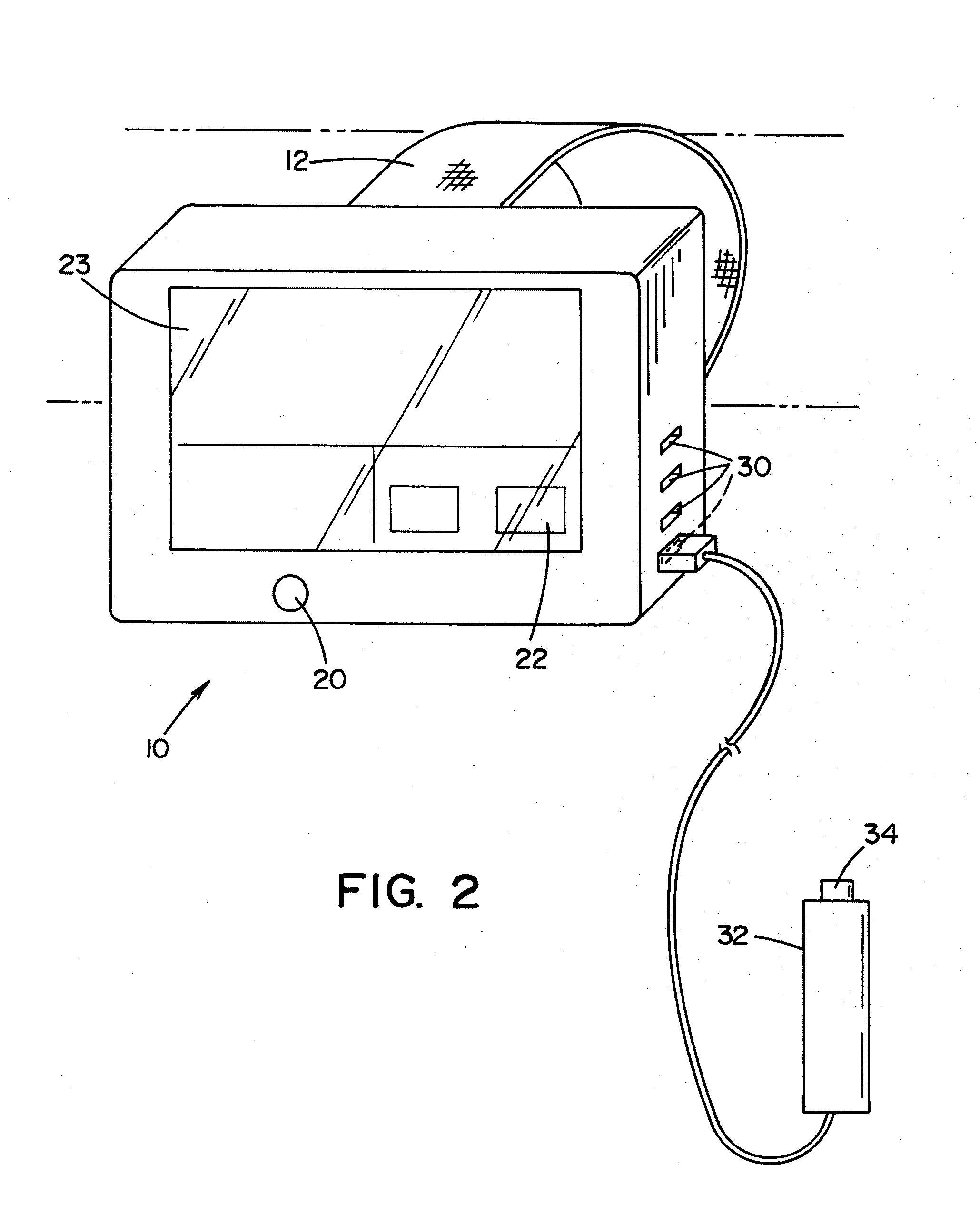
[0029]Referring now to the drawings wherein the showings are for the purposes of illustrating preferred and alternative embodiments of the invention only and not for the purpose of limiting the same, FIG. 1 shows a site plan of a jobsite JS and FIG. 2 shows a system 8 that includes a portable device 10 for use by a technician T which according to one set of embodiments, is located at jobsite JS. The remaining figures show several screen shots from portable device 10 all of which will be described in greater detail below.

[0030]Again, the invention of this application relates to monitoring system 8 and device 10 for the installation of piles along with the method of performing the same. Further, it has been found that the system and device work particularly well for auger cast piles wherein it will be described with particular reference to these cast piles. However, this application is not to be limited to auger cast piles even though they will be specifically referenced in the descri...


PUM


Abstract

A system and method of monitoring the installation of a pile in a ground surface. The system and method including the use of a portable monitoring device configured to allow real time data entry and display relating to the pile(s) being installed and having at least one data entry button for at least a portion of the data entry. The device further including a display for the display of desired data to help monitor and control the installation process.

Description

[0001]This application claim priority in U.S. Provisional Patent Application Ser. No. 61 / 440,649 which was filed on Feb. 8, 2011 (PDY-34164) which is incorporated by reference herein.[0002]The invention of this application generally relates to the installation of a pile structures into a ground surface. More particularly, the invention of this application relates to a monitoring system used to evaluate one or more installation parameters to assist in the installation of a pile structure into a ground surface and the certification of thereof. Further, the invention of this application relates to a method of using this pile monitoring system.INCORPORATION BY REFERENCE[0003]Systems used to monitor the installation of a pile have been around for a number of years. McVay et al.—U.S. Pat. No. 6,533,502 discloses a wireless apparatus and method for analysis of piles which is incorporated by reference herein for showing the same. In addition, Mullins et al.—U.S. Pat. No. 6,783,273 discloses...

Claims


Application Information

Patent Timeline
Patent Type & Authority Applications(United States)
IPC IPC(8): G06F19/00
CPCE02D7/00
Inventor DALTON, WAYNEPISCSALKO, GEORGE R.BRINKERHOFF, PAUL
Owner PILE DYNAMICS
Why Eureka
Try Eureka