Automated test tool interface

a test tool and interface technology, applied in the field of web applications, can solve the problems of affecting the accuracy of the identification process, affecting the deployment of new web applications or of new features in existing applications, and users becoming less and less tolerant of web applications that do not perform properly, etc., to achieve the effect of accurate identification

Active Publication Date: 2012-08-09
ORACLE INT CORP
View PDF19 Cites 43 Cited by
  • Summary
  • Abstract
  • Description
  • Claims
  • Application Information

AI Technical Summary

Benefits of technology

[0008]An automated test tool interface is described. A developer of a reusable web component provides an interface for obtaining an accurate identification of a root element of a component and any sub elements within the root element on a web page. An automated test framework uses this interface when recording automated tests to obtain a stable identification of the element that is independent of the rendering of the component on the web page. When the automated test is played back, the test framework again uses the interface to convert the stable identification of the element to a form that is dependent on the rendering of the component on the web page. Thus, changes in the rendering of a component will no longer cause an automated test tool to fail, as element identification in the testing framework is no longer tied to the specific rendering of the web page.

Problems solved by technology

Because of this reliance, users are becoming less and less tolerant of web applications that do not perform properly.
Although the need for thorough testing of web applications is clear, the testing phase can be extremely costly.
Each of these iterations requires the time of the tester and can delay deployment of a new web application or of new features in an existing application.
Unfortunately, currently available automated test frameworks are quite brittle in that minor changes made to a web page as a result of bug fixes can cause the recorded test plan to become invalid and the execution of the test plan to fail.

Method used


Image

  • Automated test tool interface
  • Automated test tool interface
  • Automated test tool interface

Examples


Embodiment Construction

[0024]In the following description, for the purposes of explanation, specific details are set forth in order to provide a thorough understanding of the embodiments of the invention. However, it will be apparent that the invention may be practiced without these specific details.

[0025]Embodiments of the present invention provide an automated test tool interface. The automated test tool interface may be used by an automated test framework when recording tests executed on a web application. The recorded tests are not dependent on a specific rendering of a web page within the web application. In one embodiment, techniques are provided that allow an automated testing framework to utilize the automated test tool interface to record tests that continue to work even if the rendering of the web page changes from when the test is recorded to when the test is played back.

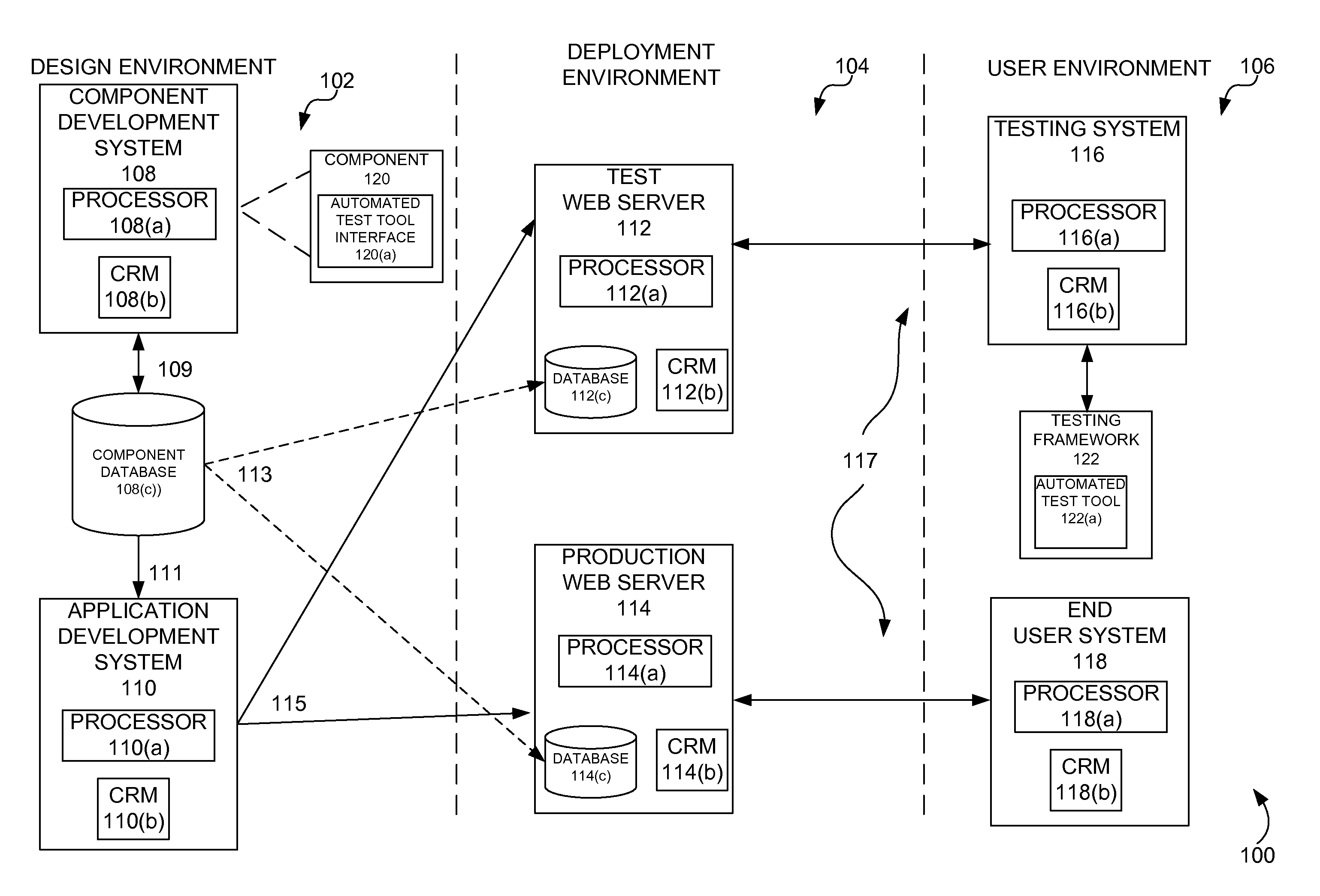
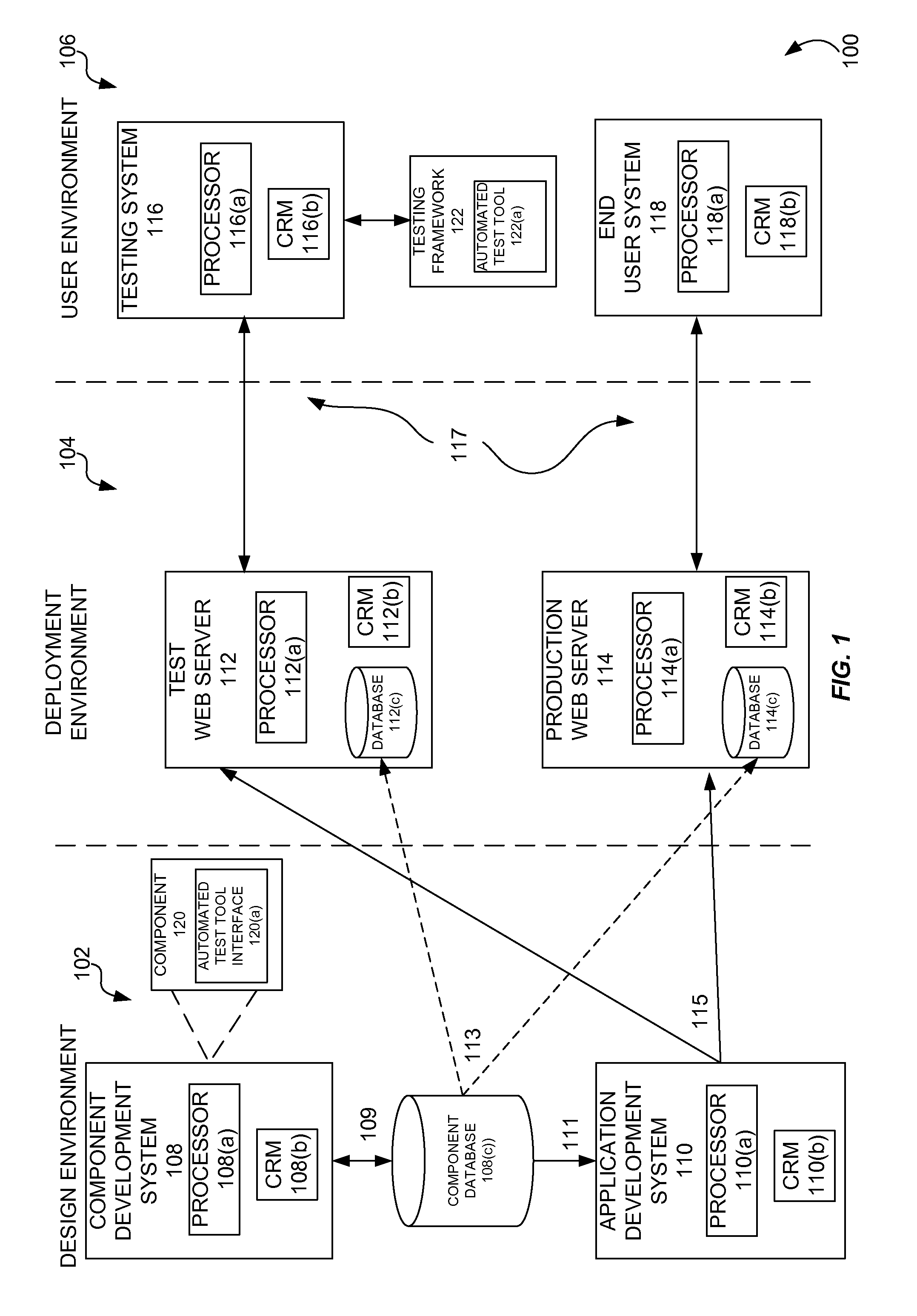
[0026]FIG. 1 is a simplified block diagram of a system 100 that may incorporate an embodiment of the present invention. The e...


PUM


Abstract

An automated test tool interface is described. A developer of a reusable web component provides an interface for obtaining an accurate identification of a root element of a component and any sub elements within the root element on a web page. An automated test framework uses this interface when recording automated tests to obtain a stable identification of the element that is independent of the rendering of the component on the web page. When the automated test is played back, the test framework again uses the interface to convert the stable identification of the element to a form that is dependent on the rendering of the component on the web page. Thus, changes in the rendering of a component will no longer cause an automated test tool to fail, as element identification in the testing framework is no longer tied to the specific rendering of the web page.

Description

BACKGROUND[0001]Embodiments of the present invention relate to web applications and more specifically to an automated test tool interface.[0002]The World Wide Web (“the Web”) has undergone an extraordinary degree of evolution. What began as a simple format for exchanging documents in a platform independent manner has morphed into technology that enables access to a seemingly unlimited amount of information at any time and any place. Web pages today include active content, as provided by browser side scripting languages such as JavaScript. Web pages can be updated in real-time using technologies such as AJAX. Static web pages being served to users via relatively unintelligent web servers have been replaced by dynamically generated web pages that are created on the fly by the web server and which are responsive to input provided by the users.[0003]In a modern web application development environment, a developer may use one or more application development frameworks in order create a w...

Claims


Application Information

Patent Timeline
Patent Type & Authority Applications(United States)
IPC IPC(8): G06F17/00
CPCG06F11/3664
Inventor SULLIVAN, BLAKESUBRAMANIAM, PAVITRAYVANOVICH, MARK
Owner ORACLE INT CORP
Why Eureka
Try Eureka