Apparatus for Defeating Threat Projectiles
a technology of armor and projectiles, applied in the field of armor systems, can solve the problems of heavy armor thickness, heavy and expensive extra armor thickness, and the possibility of affecting the system and personnel of the vehicle,
- Summary
- Abstract
- Description
- Claims
- Application Information
AI Technical Summary
Problems solved by technology
Method used
Image
Examples
second embodiment
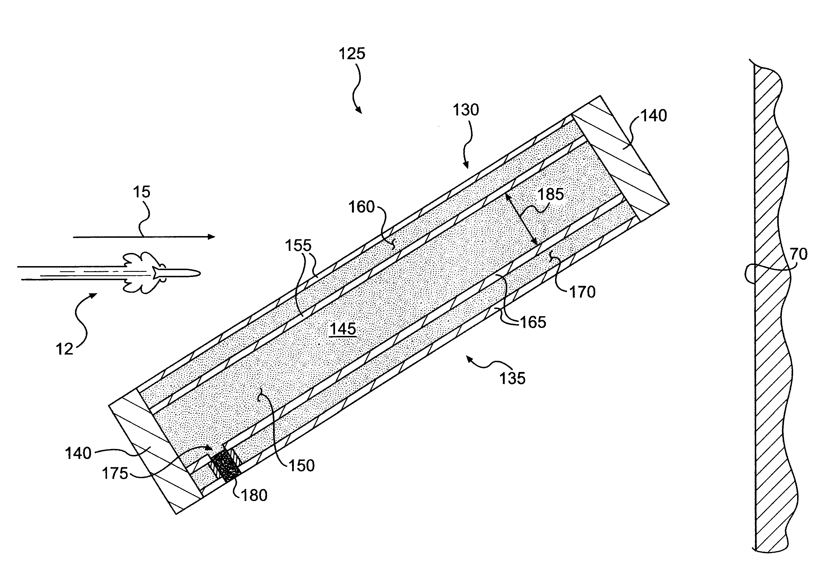
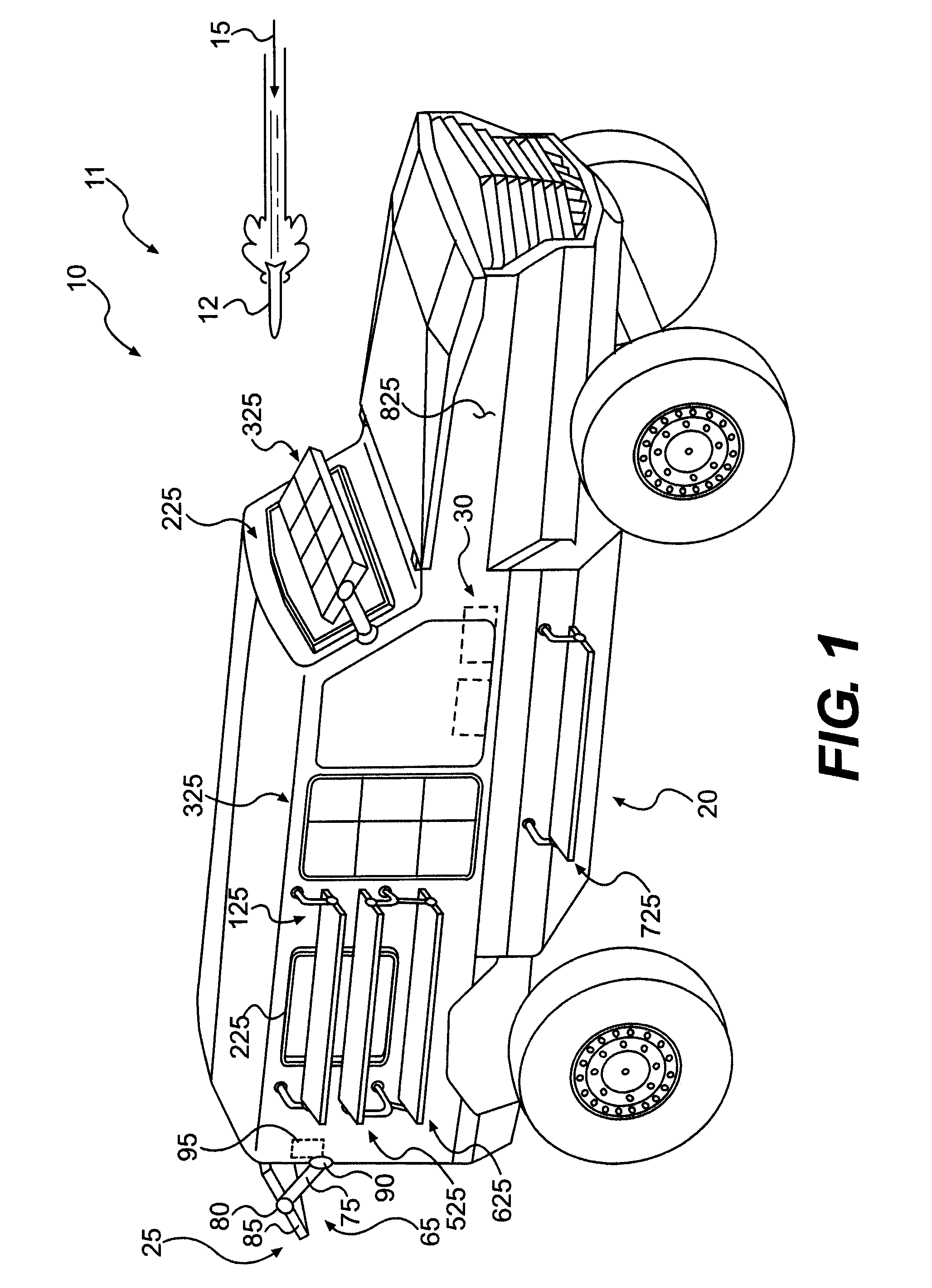
[0039]FIGS. 1 and 3 depict a second embodiment, armor subsystem 125, of armor system 10. As best seen in FIG. 3, armor subsystem 125 may include a first element 130, a second element 135, and a plurality of spacing elements 140. First element 130, second element 135, and spacing elements 140 may form a cavity 145 that holds a fill 150. Armor subsystem 125 may also include a mount assembly similar to mount assembly 65 of armor subsystem 25. Spacing elements 140 may be similar to spacing elements 45 of armor subsystem 25, and cavity 145 may be similar to cavity 50 of armor subsystem 25.
[0040]First element 130 may lead second element 135 relative to trajectory 15. First element 130 may include a plurality of layers 155 and an intermediate layer 160 that may be disposed between layers 155. Layers 155 may be sheet-like layers including material such as, for example, glass, transparent ceramics, acrylic, polycarbonate, aluminum, delrin, UHMW PP, UHMW PE, and / or borosilicate. Layers 155 ma...
third embodiment
[0043]FIGS. 1 and 4 depict a third embodiment, armor subsystem 225, of armor system 10. Referring to FIG. 4, armor subsystem 225 may include a layer 230, at least one transparent armor layer 235, at least one seal 240, and at least one frame element 245. Layer 230, transparent armor layer 235, and seal 240 may be supported by frame element 245 and may form a cavity 250 that holds a fill 255.
[0044]Layer 230 may lead transparent armor layers 235 relative to trajectory 15, and layer 230 may be similar to first layer 35 and second layer 40 of armor subsystem 25. To facilitate use in a window of vehicle 11, layer 230 may include a transparent material. Layer 230 may be spaced apart from the at least one transparent armor layer 235.
[0045]The one or more transparent armor layers 235 may include glass, transparent ceramics, acrylic, polycarbonate, and / or borosilicate. Transparent armor layer 235 may be of any suitable thickness such as, for example, between about ⅛″ and about 6″ thick.
[0046...
fourth embodiment
[0048]FIGS. 1, 5, and 6 depict a fourth embodiment, armor subsystem 325, of armor system 10. Referring to FIGS. 5 and 6, armor subsystem 325 may include a modular array 330, a support system 335 for providing structural support to modular array 330, and a filling system 340 for providing modular array 330 with fill.
[0049]As depicted in FIG. 6, which is a sectional view of FIG. 5, modular array 330 may include a ballistic module 345, a plurality of fill modules 350, and a spall module 355. Ballistic module 345 may provide protection against ballistic threats to vehicle 11, fill modules 350 may provide additional protection against threats to vehicle 11, and spall module 355 may provide protection against spalling of armor system 10. Ballistic module 345, fill modules 350, and spall module 355 may be connected by any suitable technique known in the art such as, for example, by welding or by mechanical fasteners.
[0050]Ballistic module 345 may be a ballistic-resistant layer that leads f...
PUM
 Abstract
Description
Claims
Application Information
 - R&D
- Intellectual Property
- Life Sciences
- Materials
- Tech Scout
- Unparalleled Data Quality
- Higher Quality Content
- 60% Fewer Hallucinations
Browse by: Latest US Patents, China's latest patents, Technical Efficacy Thesaurus, Application Domain, Technology Topic, Popular Technical Reports.
© 2025 PatSnap. All rights reserved.Legal|Privacy policy|Modern Slavery Act Transparency Statement|Sitemap|About US| Contact US: help@patsnap.com


