Subsurface Safety Valve for High Temperature and High Pressure Wells

a safety valve and high temperature technology, applied in the direction of hose connection, sealing/packing, borehole/well accessories, etc., can solve the problems of low contact pressure on the load bearing surface, external pressure leakage problems, and significant reduction of so as to improve the compliance of the metal to metal seal, improve the contact pressure, and improve the effect of the sealing

Inactive Publication Date: 2012-08-16
TEJAS RES & ENG
View PDF4 Cites 2 Cited by
  • Summary
  • Abstract
  • Description
  • Claims
  • Application Information

AI Technical Summary

Benefits of technology

[0008]The invention disclosed herein overcomes the problems of the prior art mentioned above by providing an annular recess at the load bearing shoulder at the joint of the tubular members. This improves the metal to metal seal compliance and improves the contact pressure on the load bearing shoulder from the torque make-up to help create high break-out torques.

Problems solved by technology

However, this solution has two serious adverse drawbacks.
Thicker tubular connections will result in lower contact pressure on the load bearing surface due to the increased contact area at the same makeup torque.
Secondly, the compliance of the metal to metal seal will be significantly decreased which will lead to external pressure leakage problems.
The portions of the upper tubular member near the inner and outer regions around the piston bore are subject to increased stresses which cause failure at these areas.

Method used


Image

  • Subsurface Safety Valve for High Temperature and High Pressure Wells
  • Subsurface Safety Valve for High Temperature and High Pressure Wells
  • Subsurface Safety Valve for High Temperature and High Pressure Wells

Examples


Embodiment Construction

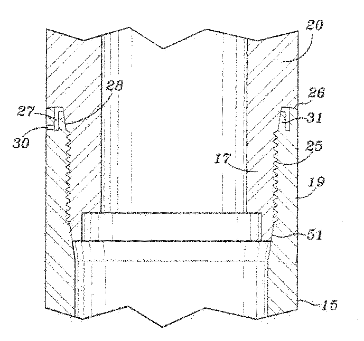
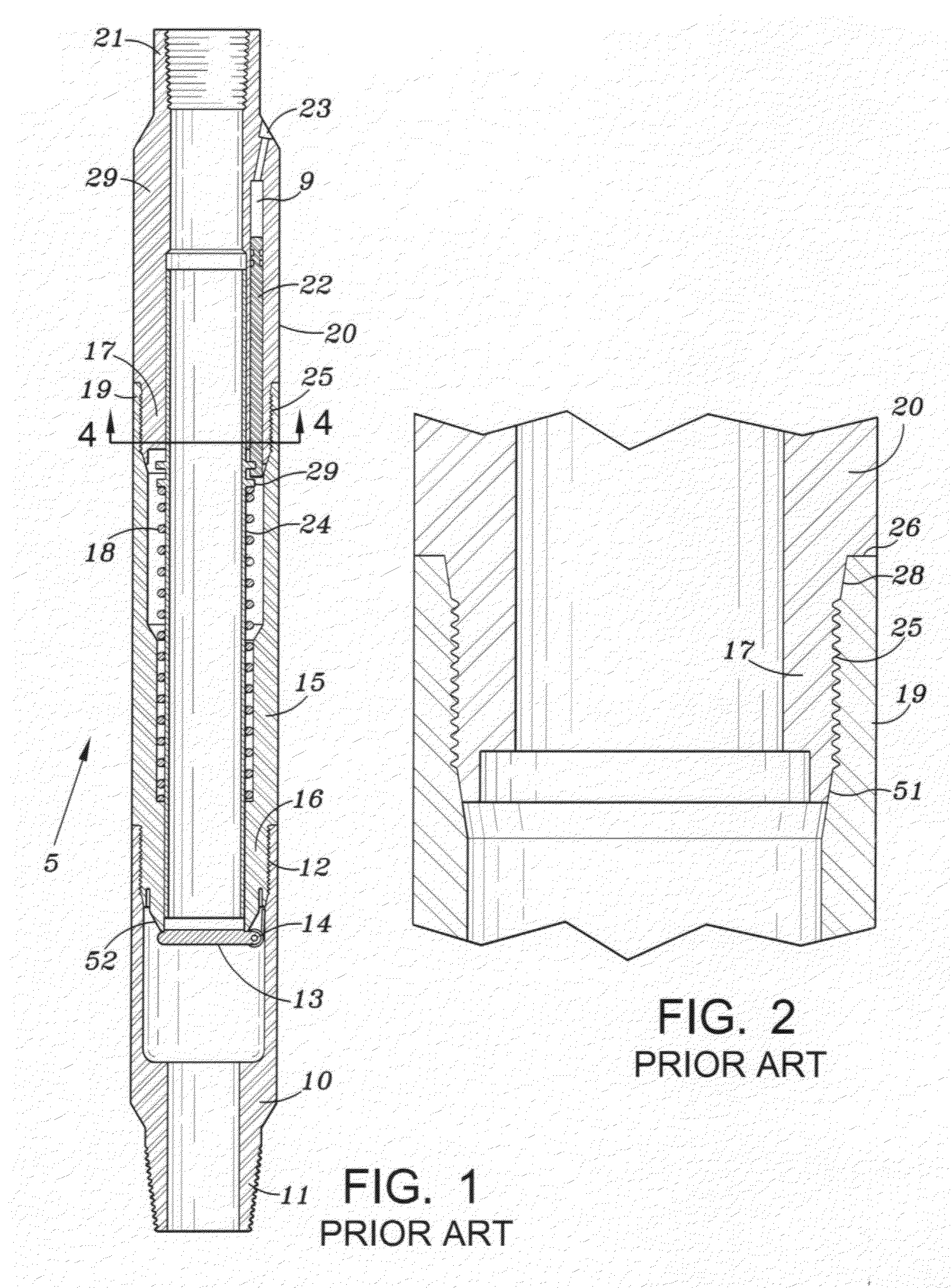
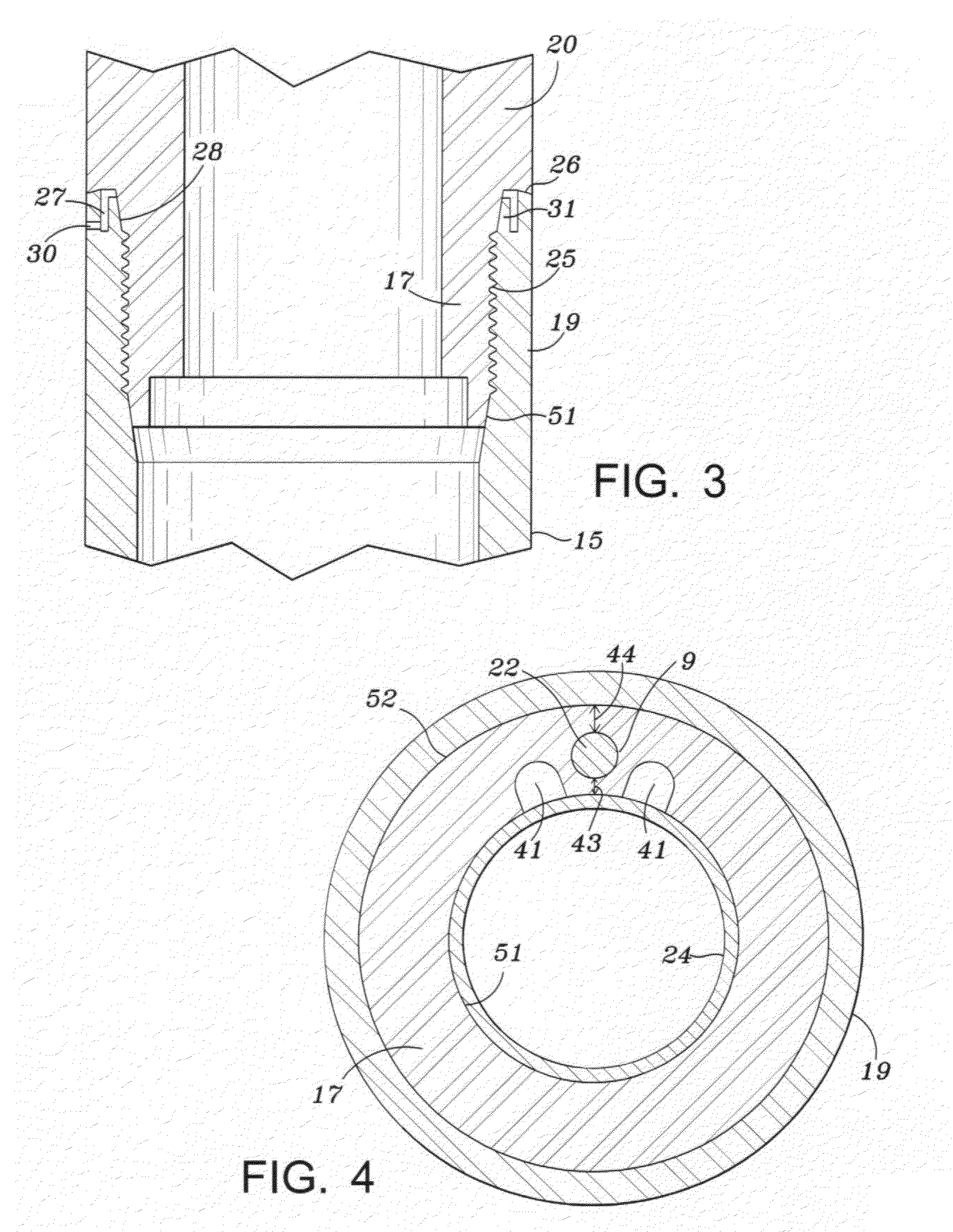
[0014]A typical subsurface safety valve 5 is shown in FIG. 1. and includes an upper tubular member 29 having a conventional coupling 21 for connection to a production tubular for example. The middle portion 20 of the top upper tubular member includes an inlet port 23 for hydraulic fluid and a piston 22 located within piston bore 9. The lower portion 17 of the upper tubular member 20 includes a pin connection that is threadly connected to upper portion 19 of the valve body housing 15 at 25, see FIG. 2. The connection between the upper tubular member 20 and valve body housing includes a load bearing shoulder at 26 and a compliant metal to metal seal at 28. Flapper valve 13 and hinge 14 are carried by the lower portion 16 of the valve body housing 15. A hollow sleeve 24 and a spring 18 which abuts a shoulder 29 on the sleeve 24 are located within the valve housing. A lower tubular member 10 is threadly connected to valve body 15 at 12 and includes a lower portion 11 for attachment to p...


PUM


Abstract

A subsurface safety valve particularly designed for high temperature and high pressure applications has an improved tubular joint connection that provides for a compliant metal to metal seal without adversely affecting the break out torque. The valve also includes axially extending grooves in the inner surface of the tubular housing in the area of a actuating piston bore to relief stresses in that area thereby reducing the risk of stress failure.

Description

BACKGROUND OF INVENTION[0001]1. Field of the Invention[0002]This invention is directed to a subsurface safety valve for oil and gas wells. The invention is particularly useful in a high pressure, high temperature well environment which is becoming more common due to the increased depth of many wells being drilled today.[0003]2. Description of Related Art[0004]Current subsurface safely valves normally include an upper tubular member 29, a valve body housing 15, and a lower tubular member 10 as shown in FIG. 1. A flapper type valve 13 is located in the valve body housing. Threaded connections are located at the juncture of the upper and lower tubular housing for connection to the valve body housing. Upper tubular member 20 includes a bore 9 in which a piston 22 is located for axial movement. A change in the pressure above and below the piston causes the piston to move, which in turn allows a compressed spring 18 to force a valve tube 24 upwards. This movement allows the flapper valve ...

Claims


Application Information

Patent Timeline
Patent Type & Authority Applications(United States)
IPC IPC(8): E21B34/06E21B17/042F16L15/04
CPCF16L15/009E21B2034/005E21B17/042E21B34/102E21B2200/05
Inventor MAILAND, JASON C.
Owner TEJAS RES & ENG
Why Eureka
Try Eureka