Strap
a technology of straps and straps, applied in the field of straps, can solve problems such as difficulty in performing length adjustments in a state, and achieve the effect of facilitating length adjustments
- Summary
- Abstract
- Description
- Claims
- Application Information
AI Technical Summary
Benefits of technology
Problems solved by technology
Method used
Image
Examples
first embodiment
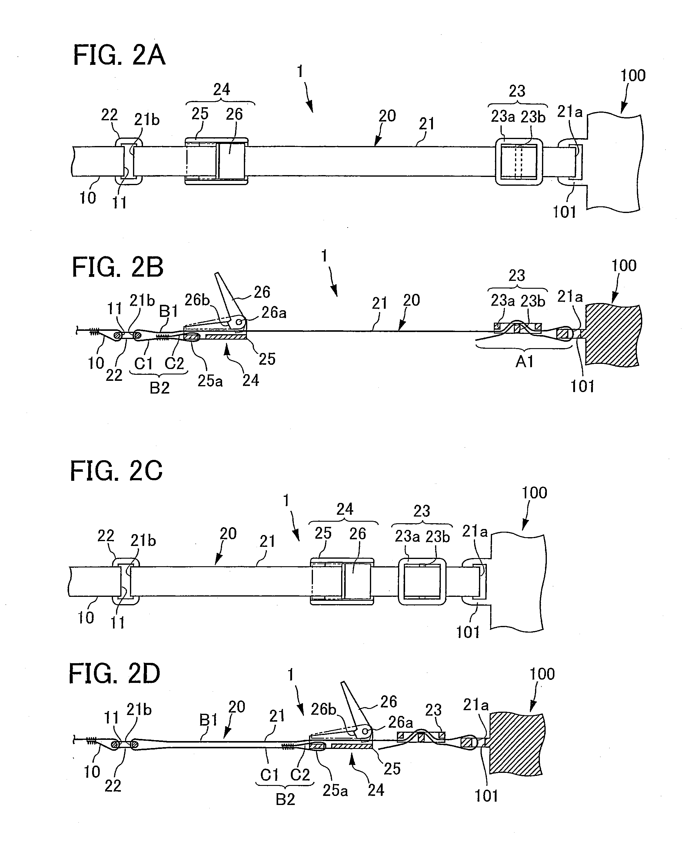
[0021]Herebelow, embodiments of a strap employing the present invention will be described with reference to the attached drawings. The following embodiments are described with a strap for a camera being taken as an example of the strap.
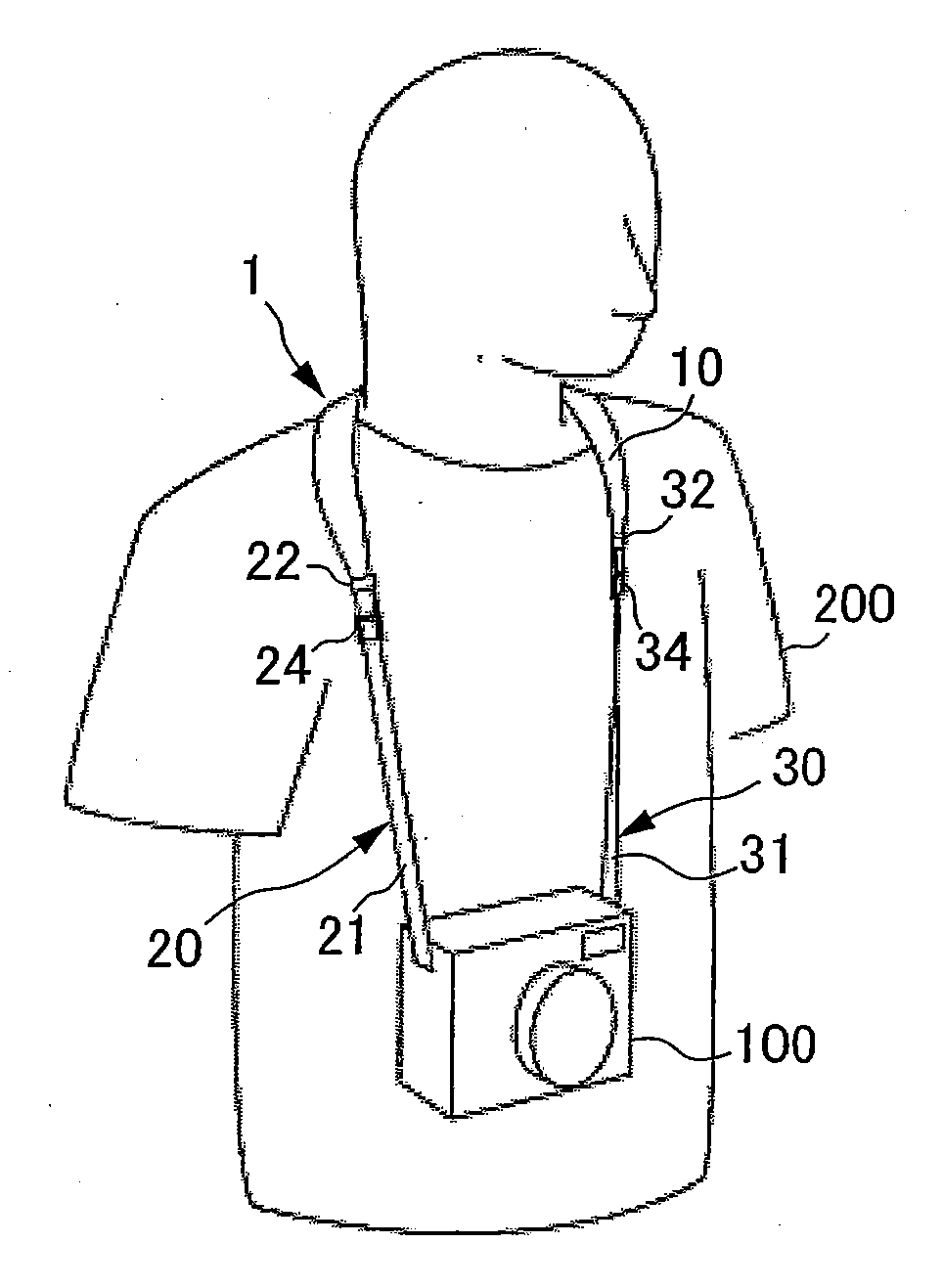
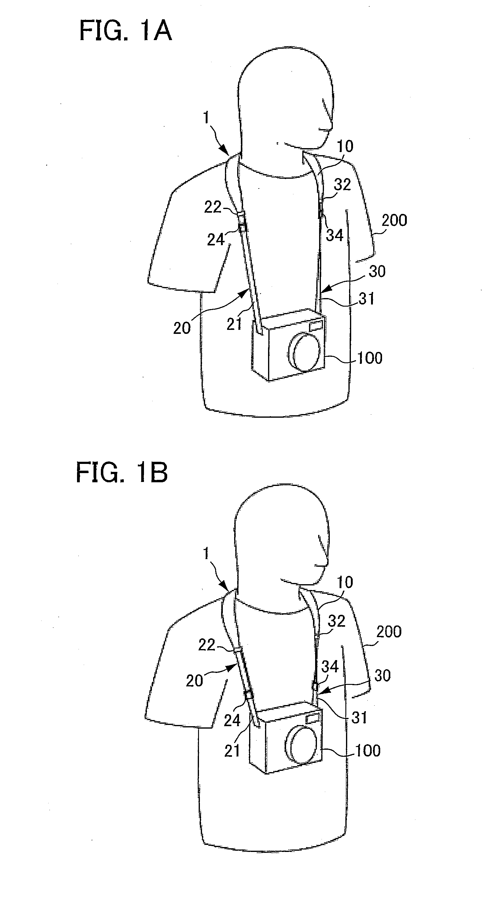
[0022]FIG. 1A and FIG. 1B are views showing examples of a usage example of a first embodiment of the strap, showing a state in which, using the strap, the camera is hung round the neck of a user. FIG. 1A shows a state in which the overall length of the strap is longer than in FIG. 1B.
[0023]The overall shape of a strap 1 is a belt shape. One length direction end portion thereof is connected to one side face of a camera 100, and the other length direction end portion is connected to another side face of the camera 100. In FIG. 1A and FIG. 1B, the strap 1 is used with a length direction middle portion being hung round the neck of a user. However, the strap 1 may be hung round another portion of the body for use, such as a shoulder of a user 200.
[0024]The...
second embodiment
[0063]Next, a second embodiment of the strap employing the present invention will be described. In this second embodiment and in other embodiments to be described later, portions performing functions the same as in the above-described first embodiment are assigned the same reference numerals, or reference numerals with matching suffixes, and duplicative descriptions and drawings are omitted as appropriate.
[0064]FIG. 3A to FIG. 3D are views showing an extensible portion provided in the second embodiment of the strap.
[0065]A strap 2 of this second embodiment differs from the strap 1 of the first embodiment in the structure of a connection portion 42, which connects the hanging portion 10 with a first extensible portion 40, and in the structure of a second adjuster 44, which is the locking mechanism. Herebelow, these differences will be described.
[0066]Whereas the connection portion 22 of the first embodiment is a rectangular ring, that is, a ring with a single hole, the connection por...
third embodiment
[0075]Next, a third embodiment of the strap employing the present invention will be described.
[0076]FIG. 4A and FIG. 4B are views showing the third embodiment of the strap.
[0077]A strap 3 of the third embodiment is a variant embodiment of the strap of the first embodiment, and is provided with a roller 52a at a portion at which a connection portion 52, which connects a first extensible portion 50 with the hanging portion 10, slidably supports a loopback end portion 51b of a main body portion 51. The rotation axis of this roller 52a is parallel with the width direction of the strap 3. The loopback end portion 51b of the main body portion 51 is wound on the outer peripheral surface of the roller 52a.
[0078]This third embodiment of the strap 3 can moderate the friction force generated between the main body portion 51 and the connection portion 52 when the same are sliding. Therefore, length adjustment of the strap 3 can be performed more easily, and usability is improved.
PUM
 Abstract
Description
Claims
Application Information
 - R&D
- Intellectual Property
- Life Sciences
- Materials
- Tech Scout
- Unparalleled Data Quality
- Higher Quality Content
- 60% Fewer Hallucinations
Browse by: Latest US Patents, China's latest patents, Technical Efficacy Thesaurus, Application Domain, Technology Topic, Popular Technical Reports.
© 2025 PatSnap. All rights reserved.Legal|Privacy policy|Modern Slavery Act Transparency Statement|Sitemap|About US| Contact US: help@patsnap.com


