Eureka AIR delivers breakthrough ideas for toughest innovation challenges, trusted by R&D personnel around the world.

Charging current control method, electronic device, and power supply device

a technology of electronic devices and current control methods, applied in the direction of resistance/reactance/impedence, instruments, transportation and packaging, etc., can solve the problems of reducing charging speed, affecting the charging speed, so as to increase the impedance of the mainboard

Pending Publication Date: 2022-02-24
GUANGDONG OPPO MOBILE TELECOMM CORP LTD
View PDF0 Cites 0 Cited by
  • Summary
  • Abstract
  • Description
  • Claims
  • Application Information

AI Technical Summary

Benefits of technology

The present patent provides a charging current control method that avoids or reduces the influence of the impedance of the mainboard on the adjustment of the output current of the power supply device. This method determines the target impedance in a charging circuit without including the impedance of the mainboard, which avoids blindly adjusting a quick charging current or exiting a quick charging mode due to the increase in impedance of the mainboard. The result is an improved charging control method that ensures efficient charging of electronic devices.

Problems solved by technology

In that case, abnormal heating will be generated in some local devices on a charging circuit, resulting in a condition of severe burnout.
However, the mainboard can actually withstand higher currents.
In this case, adjusting the quick charging current or exiting the quick charging mode will cause the charging speed to decrease and the charging time is too long.

Method used


Image

  • Charging current control method, electronic device, and power supply device
  • Charging current control method, electronic device, and power supply device
  • Charging current control method, electronic device, and power supply device

Examples


Embodiment Construction

[0045]The following will clearly and completely describe technical solutions in embodiments of the present disclosure in conjunction with drawings in the embodiments of the present disclosure. Obviously, the described embodiments are a part of the embodiments of the present disclosure, rather than all the embodiments. Based on the embodiments in the present disclosure, all other embodiments obtained by those skilled in the art without creative work shall fall within the protection scope of the present disclosure.

[0046]In order to understand the present disclosure more clearly, a working principle of quick charging will be introduced below to facilitate understanding of the subsequent solution of the present disclosure. However, it should be understood that the content introduced below is only for a better understanding of the present disclosure, and should not specifically limit the present disclosure.

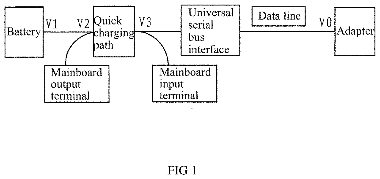
[0047]FIG. 1 is a schematic diagram of quick charging using an embodiment of the p...


PUM


Abstract

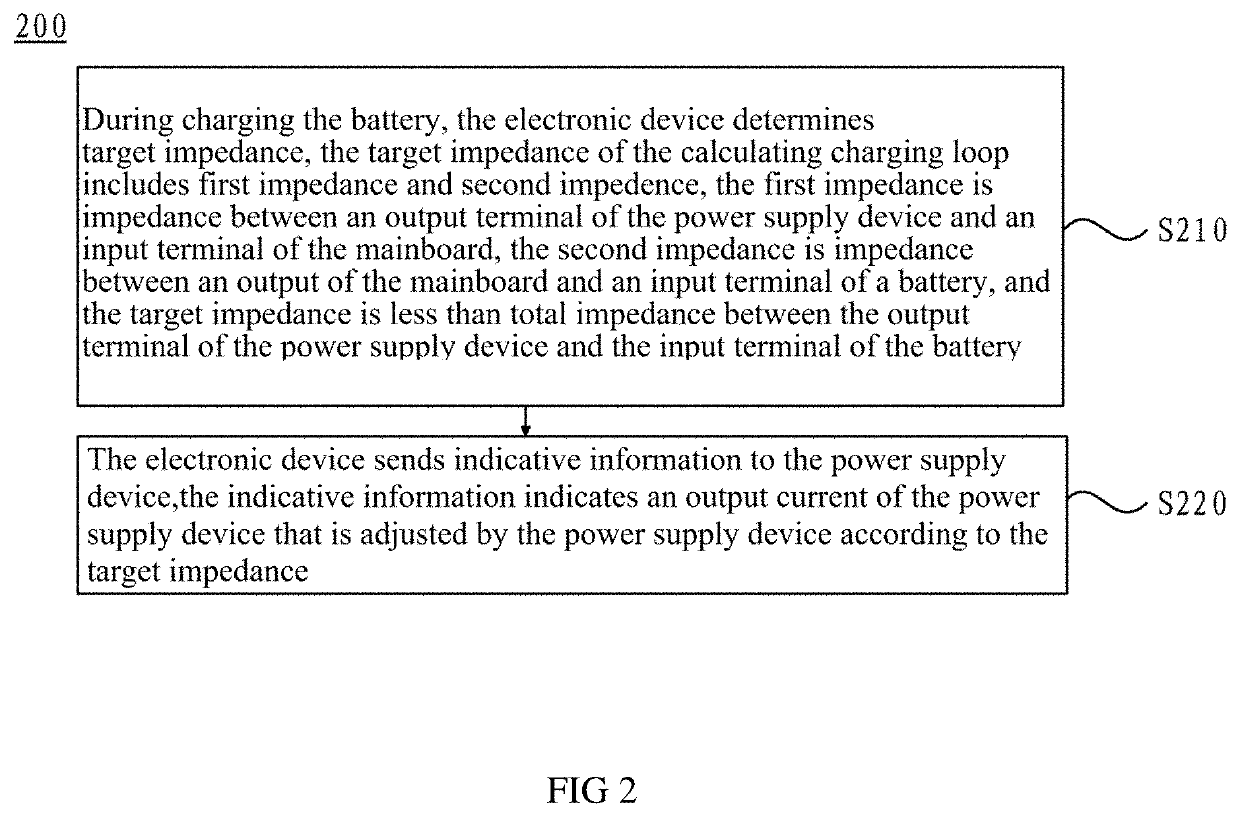
The present application provides a charging current control method, an electronic device, and a power supply device. The method comprises: in the process of charging a battery, the electronic device determines a target impedance, wherein the target impedance comprises a first impedance and a second impedance, the first impedance is an impedance between an output of the power supply device and an input of a mainboard, the second impedance is an impedance between an output of the mainboard and an input of the battery, and the target impedance is less than a total impedance between the output of the power supply device and the input of the battery; and the electronic device sends indication information to the power supply device, wherein the indication information indicates that the power supply device adjusts an output current of the power supply device according to the target impedance.

Description

CROSS-REFERENCE TO RELATED APPLICATION[0001]This application is a continuation of International Application No. PCT / CN2019 / 085875, filed on May 7, 2019, the entire disclosure of which is incorporated herein by reference in their entirety for all purposes.BACKGROUND OF DISCLOSURE1. Field of the Disclosure[0002]Embodiments of the present disclosure relate to the field of charging technology, and more specifically, to a charging current control method, an electronic device, and a power supply device.2. Description of the Related Art[0003]With popularization of electronic devices (such as mobile phones, pads, bracelets, etc.), functions of electronic devices continue to be enriched. Some manufacturers have introduced electronic devices that support quick charging modes. Quick-charging technology greatly shortens charging time of electronic devices and is widely favored by users.[0004]Currently, the quick charging technology is generally adopted in a large-current manner or a high-voltag...

Claims


Application Information

Patent Timeline
IPC IPC(8): H02J7/00G01R31/389G01R31/3842
CPCH02J7/00041G01R31/3842G01R31/389G01R27/08G01R31/36H02J7/00714H02J7/0047H02J7/00036H02J7/00032H02J7/00034H02J7/007182H02J7/007H01M10/44H02J7/00712
Inventor LIU, SHAOBINBU, CHANGJUNTIAN, CHENSHI, YANSONGLI, JIADAZHANG, JUN
Owner GUANGDONG OPPO MOBILE TELECOMM CORP LTD
Why Eureka
Eureka Blog
Learn More