Upper electrode and plasma processing apparatus

a plasma processing apparatus and upper electrode technology, applied in the direction of plasma technique, discharge tube/lamp details, non-electron-emitting electrode materials, etc., can solve the problems of dielectric member cracking, non-uniform density of plasma, stress applied, etc., and achieve the effect of improving the uniformity of plasma

Active Publication Date: 2012-08-16
TOKYO ELECTRON LTD
View PDF5 Cites 167 Cited by
  • Summary
  • Abstract
  • Description
  • Claims
  • Application Information

AI Technical Summary

Benefits of technology

The patent text describes a method to improve the uniformity of plasma using a specific electrode and plasma processing apparatus. The technical effect is to create a more consistent and reliable plasma for use in various processes.

Problems solved by technology

The technical problem addressed in this patent is the non-uniformity of plasma density in a parallel plate type plasma processing apparatus caused by the concentration of electric current at the central portion of the electrode due to the higher electric field intensity at this location. The patent proposes various solutions such as burying a dielectric member in the electrode or forming it in a tapered shape, but each has its limitations such as potential cracking of the dielectric member or non-uniformity in dimensional tolerance. The patent aims to provide a new solution to overcome these limitations and achieve higher plasma uniformity.

Method used


Image

  • Upper electrode and plasma processing apparatus
  • Upper electrode and plasma processing apparatus
  • Upper electrode and plasma processing apparatus

Examples


modification examples

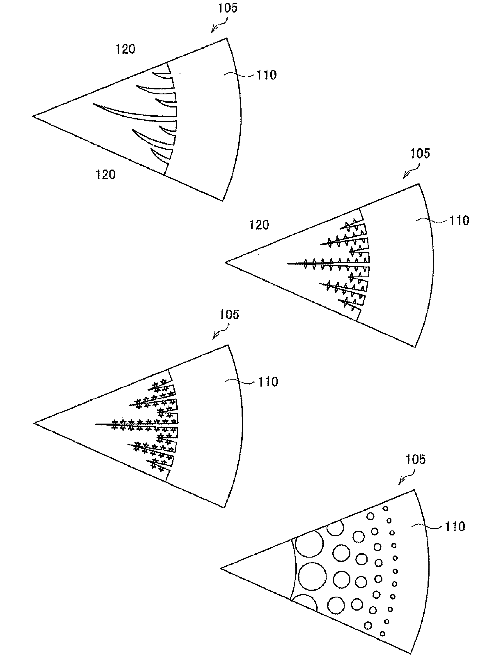
[0096]FIG. 15 illustrates modification examples of patterns formed on the conductive layer 110. FIG. 15(a) depicts a pattern having comb teeth of crescent shapes from an outer portion of the upper electrode 105 toward an inner portion thereof. Protruded portions in the middle of the crescent shapes may be arranged toward a same direction or may be symmetrically arranged toward different directions. Here, the comb teeth are arranged in an order of a longest comb tooth, a shortest comb tooth, a middle-length comb tooth, a shortest comb tooth, and a longest comb tooth. In this way, it is also possible to form a dense and sparse pattern formed on the conductive layer 110 such that the pattern at the outer portion of the upper electrode 105 is denser than at the inner portion thereof.

[0097]FIG. 15(b) illustrates a pattern similar to a comb teeth-shape protruded from an outer portion of the upper electrode 105 toward an inner portion thereof. This pattern is symmetrically arranged. Furthe...


PUM


Abstract

Plasma uniformity can be improved. An upper electrode 105 for use in a parallel plate type plasma processing apparatus includes a base 105a made of a dielectric material; and a conductive layer 110 formed on at least a part of a surface of the base 105a facing a lower electrode 210 provided in the plasma processing apparatus. Further, the conductive layer 110 having a dense and sparse pattern such that the dense and sparse pattern at an outer portion of the surface of the base 105a facing the lower electrode 210 is denser than at an inner portion thereof.

Description


Claims


Application Information

Patent Timeline
Owner TOKYO ELECTRON LTD
Why Eureka
Try Eureka