Method for RF power distribution in a multi-zone electrode array

a multi-zone electrode array and power distribution technology, applied in the direction of coatings, chemical vapor deposition coatings, electric discharge tubes, etc., can solve the problems that prior ccp processing systems may not be able to meet such uniformity requirements, and achieve the effect of enhancing the uniformity of the plasma field

Active Publication Date: 2018-01-18
TOKYO ELECTRON LTD
View PDF4 Cites 3 Cited by
  • Summary
  • Abstract
  • Description
  • Claims
  • Application Information

AI Technical Summary

Benefits of technology

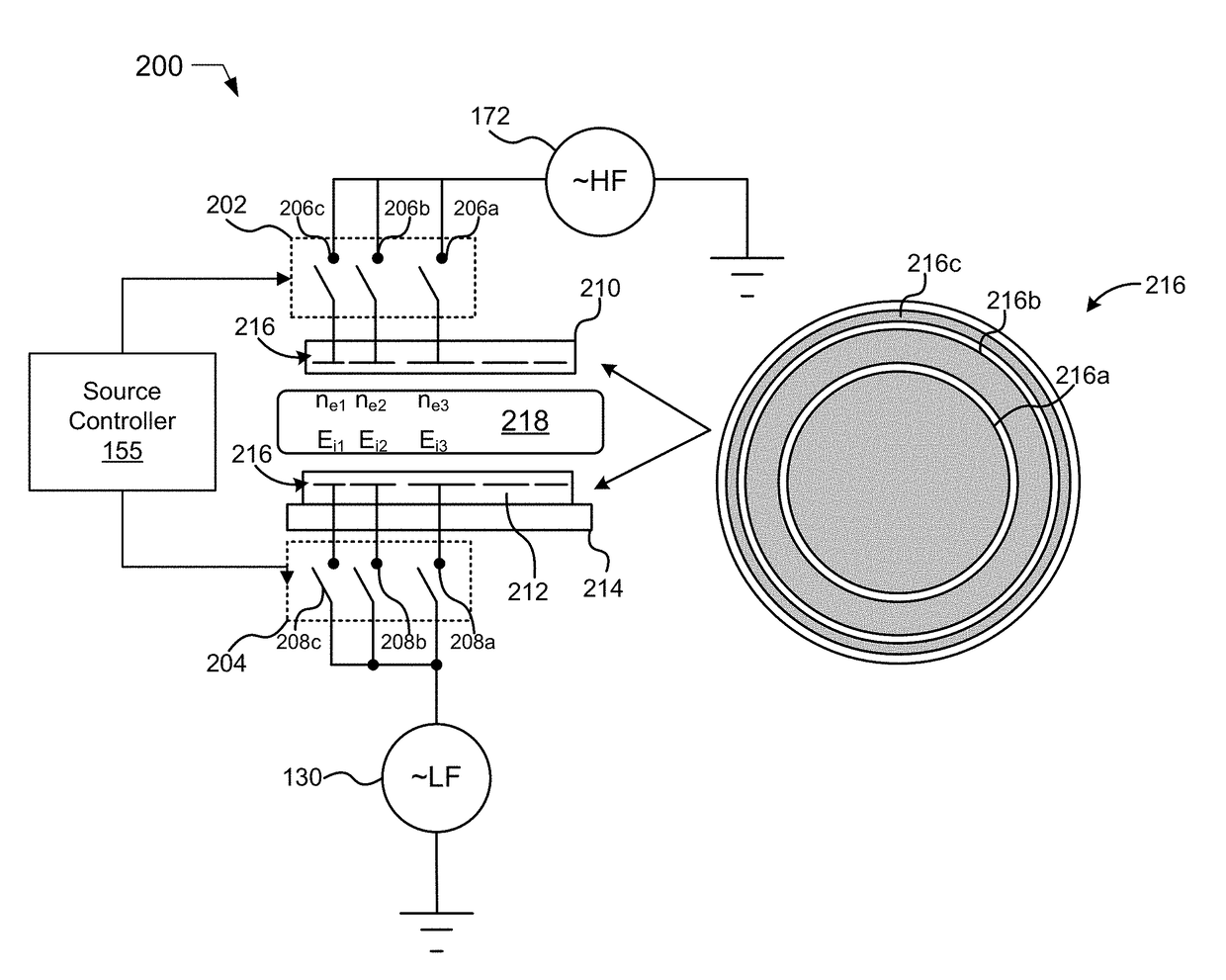
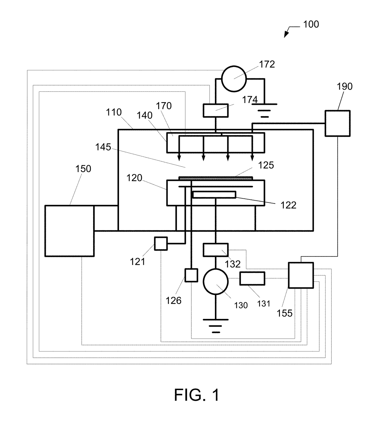
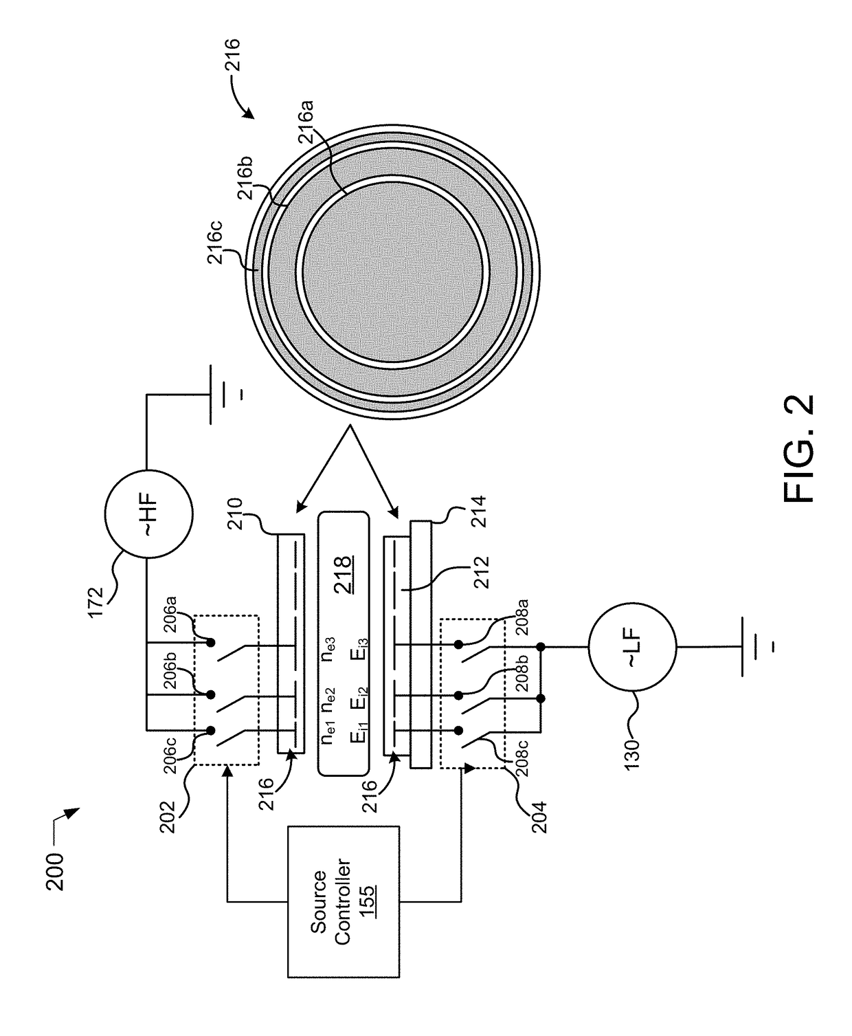
[0008]Embodiments of systems and methods for RF power distribution in a multi-zone electrode array are described. A system may include a plasma source configured to generate a plasma field. Also, the system may include an RF power source coupled to the plasma source and configured to supply RF power to the plasma source. The system may also include a source controller coupled to the RF power source and configured to control modulation of the RF power supplied to the plasma source to enhance uniformity of a plasma field generated by the plasma source.
[0009]In an embodiment, a method includes providing a plasma source configured to generate a plasma field, the plasma source having a first electrode assembly having a plurality of source electrodes and a second electrode assembly having a plurality of ring-shaped source electrodes. The method may also include supplying High Frequency (HF) Radio Frequency (RF) power to the first electrode assembly and Low Frequency (LF) RF power to the second electrode assembly with a RF power source. Additionally, the method may include selectably applying RF power to the each of the plurality of source electrodes in the first electrode assembly independently with a first multiplexer coupled to the first electrode assembly. Also, the method may include selectably applying RF power to the each of the plurality of source electrodes in the second electrode assembly independently with a second multiplexer coupled to the second electrode assembly. The method may also include controlling modulation of the RF power supplied to the plasma source to enhance uniformity of a plasma field generated by the plasma source with a source controller coupled to the first multiplexer and to the second multiplexer.

Problems solved by technology

Prior CCP processing systems may not be capable of meeting such uniformity requirements because of variation in plasma densities, including ion energy and ion flux.

Method used


Image

  • Method for RF power distribution in a multi-zone electrode array
  • Method for RF power distribution in a multi-zone electrode array
  • Method for RF power distribution in a multi-zone electrode array

Examples


Embodiment Construction

[0017]Methods and systems for RF power distribution in a multi-zone electrode array are presented. However, one skilled in the relevant art will recognize that the various embodiments may be practiced without one or more of the specific details, or with other replacement and / or additional methods, materials, or components. In other instances, well-known structures, materials, or operations are not shown or described in detail to avoid obscuring aspects of various embodiments of the invention.

[0018]Similarly, for purposes of explanation, specific numbers, materials, and configurations are set forth in order to provide a thorough understanding of the invention. Nevertheless, the invention may be practiced without specific details. Furthermore, it is understood that the various embodiments shown in the figures are illustrative representations and are not necessarily drawn to scale. In referencing the figures, like numerals refer to like parts throughout.

[0019]Reference throughout this ...


PUM

PropertyMeasurementUnit
frequencyaaaaaaaaaa
cycle timeaaaaaaaaaa
feature sizesaaaaaaaaaa

Abstract

Embodiments of systems and methods for RF power distribution in a multi-zone electrode array are described. A system may include a plasma source configured to generate a plasma field. Also, the system may include an RF power source coupled to the plasma source and configured to supply RF power to the plasma source. The system may also include a source controller coupled to the RF power source and configured to control modulation of the RF power supplied to the plasma source to enhance uniformity of a plasma field generated by the plasma source.

Description

CROSS-REFERENCE TO RELATED APPLICATIONS[0001]This application is related to and claims priority to U.S. Provisional Application No. 62 / 362,248, filed Jul. 14, 2016, the entire contents of which are herein incorporated by reference.BACKGROUND OF THE INVENTIONField of Invention[0002]The present invention relates to systems and methods for substrate processing, and more particularly to a method and system for Radio Frequency (RF) power distribution in a multi-zone electrode array.Description Of Related Art[0003]Plasma sources are used in various semiconductor device manufacturing processes, such as dry plasma etch processes. A plasma etch process is used to remove or etch material along fine lines or within vias or contact holes patterned on a semiconductor substrate. The plasma etch process generally involves positioning a semiconductor substrate with an overlaying patterned, protective layer, for example a photoresist layer, into a processing chamber.[0004]Once the substrate is posit...

Claims


Application Information

Patent Timeline
Patent Type & Authority Applications(United States)
IPC IPC(8): H01J37/32C23C16/509
CPCH01J37/32082C23C16/509H01J37/3244C23C16/5093H01J37/32174H01J37/32532
Inventor VORONIN, SERGEYRANJAN, ALOK
Owner TOKYO ELECTRON LTD
Why Eureka
Try Eureka