Plasma treatment device and structure of reaction vessel for plasma treatment

a plasma treatment and reaction vessel technology, applied in the direction of plasma technique, chemical vapor deposition coating, coating, etc., can solve the problems of uneven process gas distribution, inability to form films in a place where the standing wave occurs, and inability to achieve standing wave, so as to improve the in-plane uniformity of plasma density in plasma treatmen

Active Publication Date: 2019-02-14
CORTECH +1
View PDF3 Cites 1 Cited by
  • Summary
  • Abstract
  • Description
  • Claims
  • Application Information

AI Technical Summary

Benefits of technology

[0033]According to the present invention, the in-plane uniformity of plasma density in the plasma treatment can be improved.

Problems solved by technology

The second factor is unevenness of process gas distribution within a plasma treatment space.
When the standing wave relating to the first factor occurs, even if the process gas is uniformly distributed, plaque will occur in glow discharge generated in plasma treatment space, thus film cannot be formed in a place where the standing wave occurs.
According that treatment area becomes larger, unevenness of process gas distribution becomes easy to be generated.
Conventionally, although the process gas introduced in the plasma treatment space is supplied while passing through a shower plate in which a plurality of ventilation holes are formed and dispersed, thereby the in-plane uniformity of density of the process gas becoming material of the plasma generated on the substrate is improved, there is a problem that the process gas does not sufficiently disperse in a plane direction, film thickness formed just below a gas introduction hole becomes easy to be thick and thickness of thin film formed on the substrate becomes non-uniform.

Method used


Image

  • Plasma treatment device and structure of reaction vessel for plasma treatment
  • Plasma treatment device and structure of reaction vessel for plasma treatment
  • Plasma treatment device and structure of reaction vessel for plasma treatment

Examples


Embodiment Construction

[0049]Hereinafter, with reference to the drawings, the embodiments of the present invention will be described.

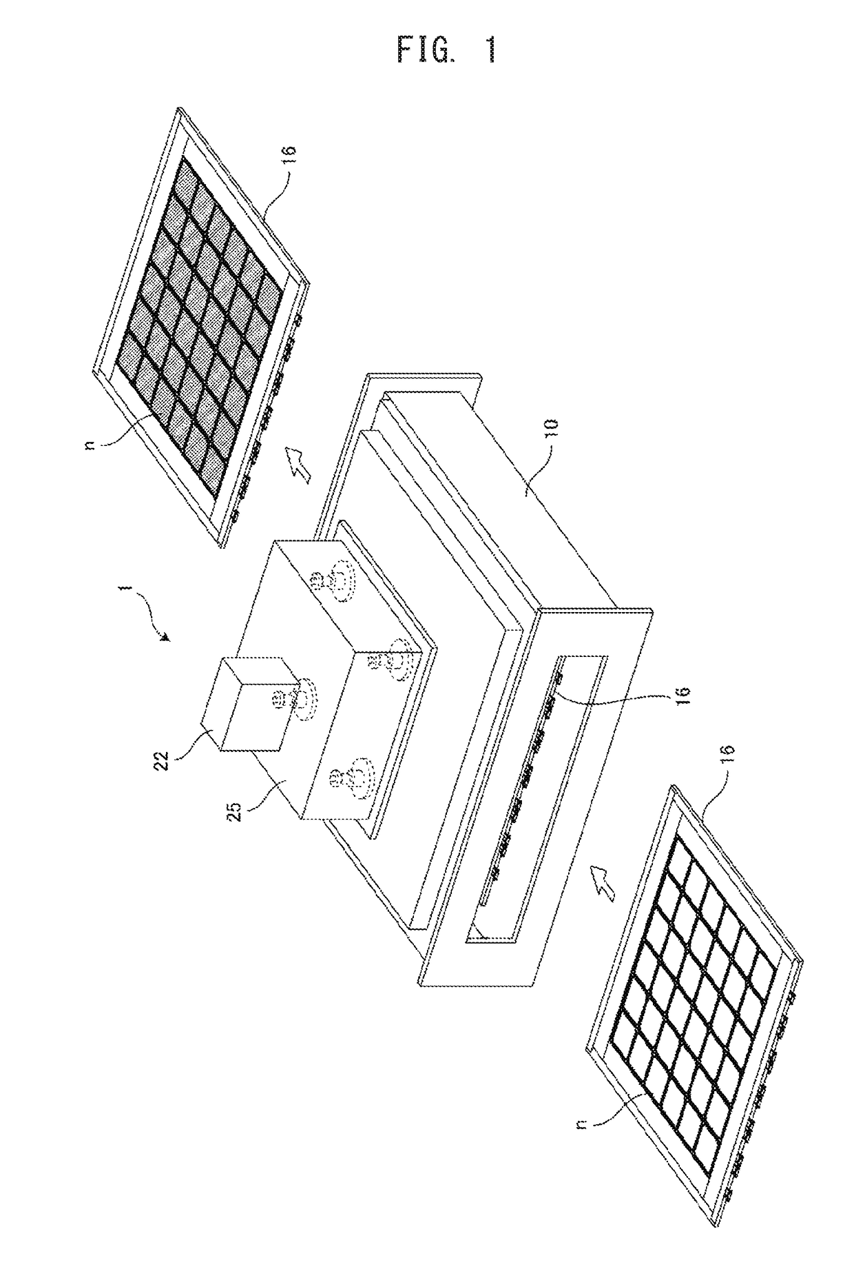
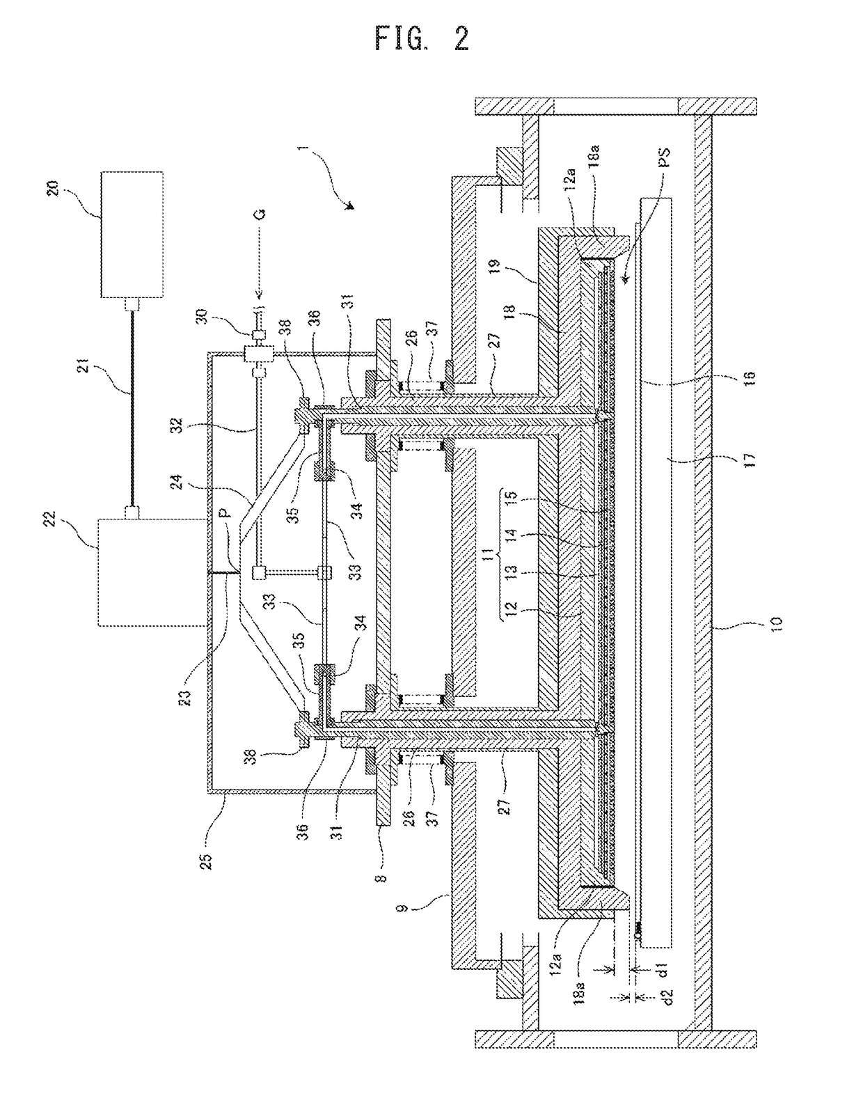
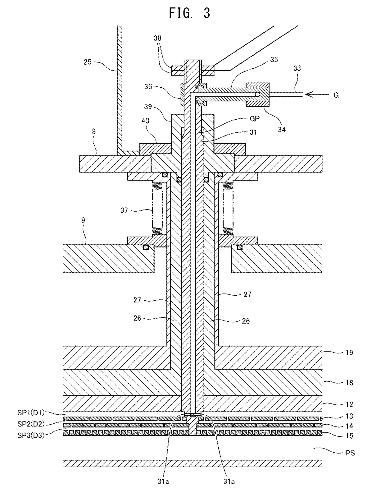
[0050]FIG. 1 is a perspective view showing a whole constitution of a plasma treatment device, FIG. 2 is an explanatory view to explain a sectional constitution of the plasma treatment device, FIG. 3 is a view in which a main part of FIG. 2 is enlarged and shown, FIG. 4 is a view in which a main part of FIG. 3 is further enlarged and shown and FIG. 5 is a view to explain sizes and positions of a plurality of small holes in each plate constituting an electrode plate.

[0051]The plasma treatment device 1 possesses a reaction vessel 10 for conducting thin film formation against an object such as semiconductor wafer and the like by utilizing plasma occurring based on that the process gas G is decomposed under reduced pressure through the high frequency glow discharge, a frequency power supply 20 for supplying frequency power to generate plasma (for example, power with a predetermin...


PUM

PropertyMeasurementUnit
diametersaaaaaaaaaa
frequencyaaaaaaaaaa
impedanceaaaaaaaaaa

Abstract

The present invention improves the in-plane uniformity of film formation via a plasma treatment. It is provided a plasma treatment device constituted so that process gas introduced between an electrode plate and a shower plate is exhausted toward a counter electrode through a plurality of small holes formed in the shower plate, the plasma treatment device comprising a diffuser plate having a plurality of small holes, the diffuser plate being arranged substantially parallel with the shower plate, wherein the process gas is introduced between the electrode plate and the diffuser plate, passes through the plural small holes of the diffuser plate, reaches the shower plate and flows out from the plural small holes of the shower plate toward the electrode plate, and wherein within the small holes formed in the diffuser plate and the small holes formed in the shower plate, the small holes formed in a plate which exists more downstream along a flowing direction of the process gas are made in smaller diameters and an aperture ratio of each plate is made smaller in a plate which exists more upstream along the flowing direction of the process gas.

Description

TECHNICAL FIELD[0001]The present invention relates to a plasma treatment device and a structure of reaction vessel for plasma treatment.BACKGROUND ART[0002]Recently, in production of electronic devices such as a FPD (Flat Panel Display) and a solar cell, it is widely used a PECVD (Plasma-Enhanced Chemical Vapor Deposition) technology in which a thin film is accumulated on a substrate by utilizing gas phase state formed by exciting and decomposing process gas through plasma.[0003]The PECVD device is more advantageous than a heat CVD device at points that precise film formation can be done at a lower temperature, heat damage and mutual diffusion between layers can be suppressed, practical accumulation speed can be obtained even if material hard to be pyrolyzed is utilized, and a thin film can be formed with various composition ratios by using plural kinds of materials each of which has a different pyrolysis temperature.[0004]On the other hand, as for in-plane uniformity of the object ...

Claims


Application Information

Patent Timeline
Patent Type & Authority Applications(United States)
IPC IPC(8): C23C16/50C23C16/455C23C16/458H01J37/32
CPCC23C16/50C23C16/45559C23C16/45565C23C16/4586H01J37/32449H01J37/32577H01J37/32018H01J37/32899H01J2237/3321H01J2237/3325H01J2237/3323C23C16/509H05H1/24H05H1/46
Inventor YOSHIMURA, TOSHIAKIMINOWA, HIROYUKISHEK, LUNG KEI AMOS
Owner CORTECH
Why Eureka
Try Eureka