
Sputtering apparatus

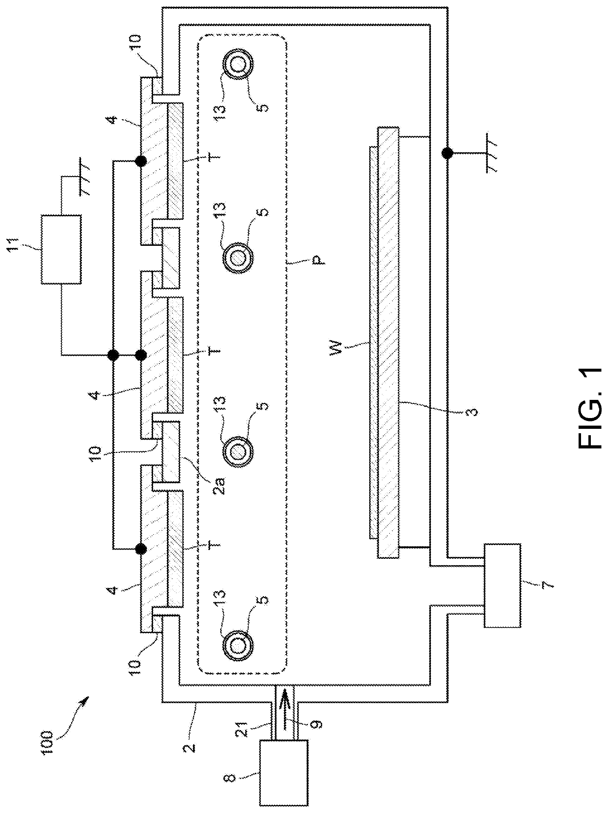
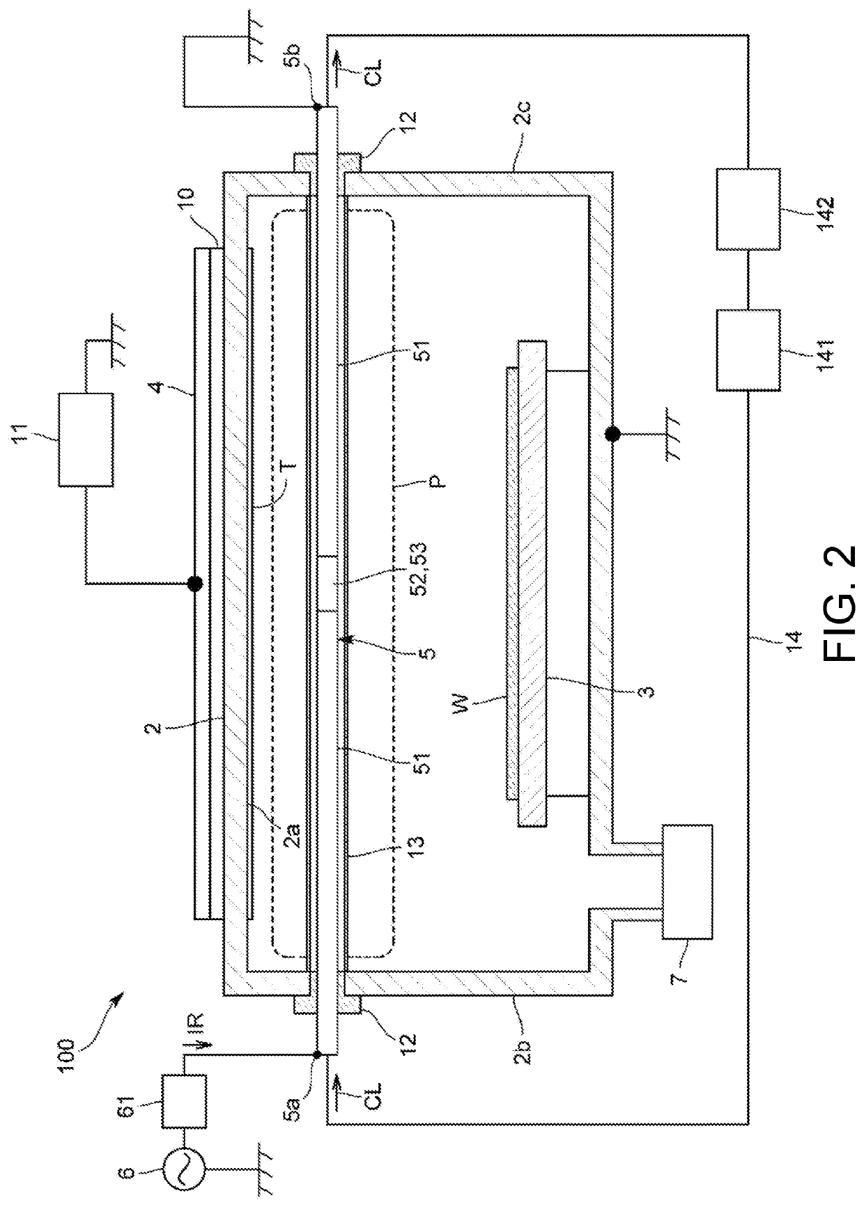
a technology of sputtering apparatus and sputtering tube, which is applied in the direction of vacuum evaporation coating, plasma technique, coating, etc., can solve the problems of large potential difference between two ends of the antenna, increase in the impedance of the antenna, uneven thickness of the film that is generated, etc., to improve the uniformity of the film formation, improve the uniformity of the plasma, and generate efficient

Active Publication Date: 2021-05-20
NISSIN ELECTRIC CO LTD
View PDF0 Cites 0 Cited by
  • Summary
  • Abstract
  • Description
  • Claims
  • Application Information

AI Technical Summary

Benefits of technology

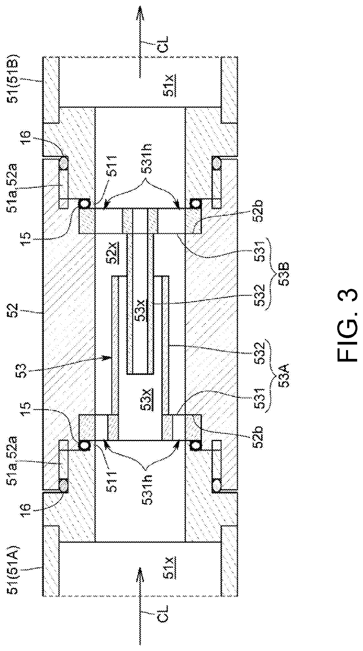
The patent text describes a sputtering apparatus that reduces the impedance of an antenna by using a capacitive element connected to adjacent conductor elements via an insulating element. This results in an improved plasma generation, increased density of plasma, and faster film forming speed. The technical effect of the apparatus is efficient plasma generation with a high frequency current easily flowing to the antenna.

Problems solved by technology

In addition, since the target is not uniformly consumed, a film that is generated also has an uneven thickness.
However, when an antenna is elongated to cope with an increase in size of a substrate in recent years, impedance of the antenna increases, and thereby a large potential difference occurs between two ends of the antenna.

Method used


Image

  • Sputtering apparatus
  • Sputtering apparatus
  • Sputtering apparatus

Examples


other modification embodiments

[0108]Moreover, the present invention is not limited to the above-described embodiment.

[0109]For example, in the embodiment, the antenna has a straight line shape; however, the antenna may have a curved or bent shape. In this case, the metal pipe may have a curved or bent shape, and the insulating pipe may have a curved or bent shape.

[0110]The extension portions of the electrode of the embodiment have a cylindrical shape; however, the extension portion may have a rectangular cylinder shape other than the cylindrical shape or may have a flat plate shape or a curved or bent plate shape.

[0111]In the embodiment, the capacitor 53 has a two-cylinder structure consisting of two extension portions having the cylindrical shape; however, as illustrated in FIG. 8, three cylindrical extension portions 532 or more may be coaxially disposed. In this case, the extension portion 532 of the first electrode 53A and the extension portion 532 of the second electrode 53B are configured to be alternately...


PUM

PropertyMeasurementUnit
relative dielectric constantaaaaaaaaaa
bias voltageaaaaaaaaaa

Abstract

The apparatus includes: a vacuum container; a substrate-holding part inside the vacuum container; a target-holding part inside the vacuum container; and a plurality of antennas having a flow channel through which a cooling liquid flows. The antennas include: at least two tubular conductor elements; a tubular insulating element that is arranged between mutually adjacent conductor elements and insulates the conductor elements; and a capacitive element that is connected electrically in series to the mutually adjacent conductor elements. The capacitive element includes: a first electrode which is connected electrically to one of the mutually adjacent conductor elements; a second electrode which is connected electrically to the other of the mutually adjacent conductor elements and is disposed facing the first electrode; and a dielectric substance that fills the space between the first electrode and the second electrode. The dielectric substance is a cooling liquid.

Description

BACKGROUND OF THE INVENTIONTechnical Field[0001]The present invention relates to a sputtering apparatus that performs sputtering on a target with plasma to form a film on a substrate.Related Art[0002]As this type of sputtering apparatus, a magnetron sputtering apparatus is known. The magnetron sputtering apparatus is configured to form a magnetic field at a front surface of a target by a magnet arranged at a back surface of the target so as to generate plasma and to cause ions in the plasma to collide with the target, and thereby cause sputtered particles to fly out from the target.[0003]In the conventional magnetron sputtering apparatus, sparseness and density plasma is generated in the vicinity of the front surface of the target. Accordingly, the target is not uniformly consumed, and a utilization rate of the target is lowered. In addition, since the target is not uniformly consumed, a film that is generated also has an uneven thickness.[0004]On the other hand, as disclosed in pat...

Claims


Application Information

Patent Timeline
Patent Type & Authority Applications(United States)
IPC IPC(8): H01J37/32H01J37/34
CPCH01J37/3211H01J37/3408H01J37/3417H05H1/46C23C14/34C23C14/08C23C14/3407C23C14/3464H01J37/32532H01J37/3222C23C14/228
Inventor KISHIDA, SHIGEAKIMATSUO, DAISUKESETOGUCHI, YOSHITAKAANDO, YASUNORI
Owner NISSIN ELECTRIC CO LTD
Learn More