
Display apparatus

a technology for display apparatus and display screen, which is applied in the direction of lighting and heating apparatus, static indicating devices, instruments, etc., can solve the problems of difficult image display, disconnected screen image, and game machine providing only a very restrictive and restrictive image, so as to simplify a manufacturing process, improve the brightness of the front backlight unit, and improve the quality

Inactive Publication Date: 2012-08-16
KORTEK CORP
View PDF11 Cites 26 Cited by
  • Summary
  • Abstract
  • Description
  • Claims
  • Application Information

AI Technical Summary

Benefits of technology

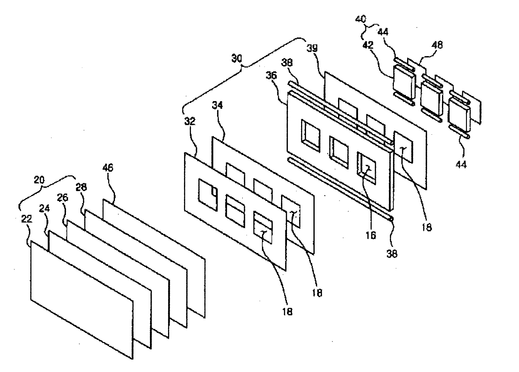
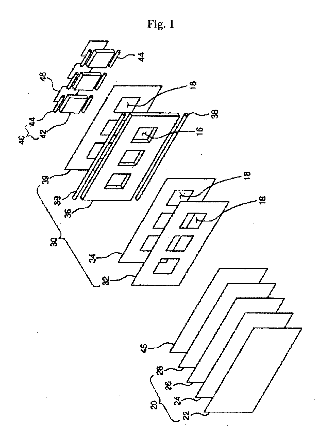
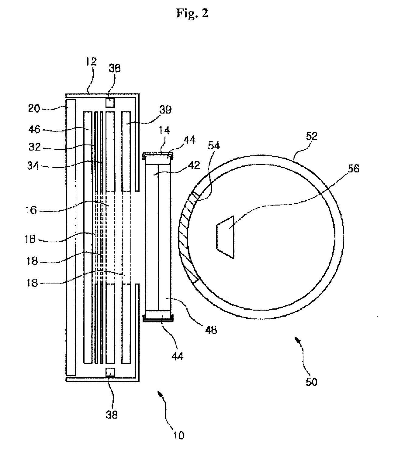
[0019]According to the present invention, the front display unit of the display apparatus is equipped with a front backlight unit having a projection window through which the rear display unit is visible, a rear backlight unit is placed corresponding to the projection window, and a rear optical shutter is placed behind the rear backlight unit. With this configuration, when the rear optical shutter is switched to a transparent state, the rear display unit may be viewed through the light guide plate of the rear backlight unit to display a combined image in cooperation with the front display unit. Further, when the rear optical shutter is shielded, the rear backlight unit illuminates a region of the front display unit corresponding to the projection window, with an image of the rear display unit completely shielded, so that the entirety of the front display unit can be illuminated, thereby allowing the front display unit to display an image on the entire screen thereof without disconnection of the screen. As a result, the display apparatus may realize display of game-related images in various ways in higher quality by allowing the game-related images to be displayed through the entire screen of the front display unit while completely blocking the rear display unit when a game is not played.
[0020]In addition, according to the present invention, the display panel is provided at the rear side thereof with a front optical shutter which is used to switch the front optical shutter to a transparent state or to a shielded state in order to indicate whether a game is played by controlling on / off of the overall screen of the display apparatus.
[0021]Further, according to the present invention, the light guide plate of the front backlight unit is formed with a pattern region and a non-pattern region to provide a projection window without cutting the light guide plate, thereby simplifying a manufacturing process of the light guide plate, improving brightness of the front backlight unit through an increase in total reflection area within the light guide plate, and suppressing light interference between the front backlight unit and the rear backlight unit by light shielding between the pattern region and the non-pattern region.
[0022]Furthermore, such effects of the present invention may be usefully applied not only to game machines such as slot machines, but also to a technique for embodying 3-dimensional and 2-dimensional images based on combination of front and rear display units, and other image display techniques based on combination of the front and rear display units.

Problems solved by technology

However, in such a game machine, light is not emitted through the opening of the light guide plate, causing disconnection of an image displayed on the liquid crystal display.
For example, when a game-related image is displayed through the liquid crystal display at the front side of the game machine, with the rear rotational reel display unit stopped, it is difficult to display the image since a backlight unit is not present in a region through which the rotational reel display unit is viewed.
As a result, the game machine provides only a very restrictive and disconnected screen image in displaying game results and guide messages through the front liquid crystal display.

Method used


Image

  • Display apparatus
  • Display apparatus
  • Display apparatus

Examples


Embodiment Construction

[0028]Embodiments of the present invention will now be described in detail with reference to the accompanying drawings.

[0029]The present invention relates to a display apparatus which displays a combined image through cooperation between a front display unit and a rear display unit disposed behind the front display unit. Such a display apparatus may be applied in various ways, for example, game machines such as slot machines, game machines which display images through combination of front and rear displays, 3D image display apparatuses, electronic frames, and the like.

[0030]According to one embodiment, a liquid crystal display and a rotational reel display unit may be used as front and rear display units, respectively. The rotational reel display unit may be configured to provide variable display of symbol marks printed on a reel band and to allow winning of a game to be determined according to combination of the symbol marks.

[0031]In another embodiment, the rear display unit may be...


PUM

PropertyMeasurementUnit
circumferenceaaaaaaaaaa
thicknessaaaaaaaaaa
brightnessaaaaaaaaaa

Abstract

The present invention relates to a display apparatus comprising front display unit (10) and rear display unit (50), wherein the front display unit (10) and the rear display unit (50) are arranged such that an image on the rear display unit (50) is visible through a portion of the front display unit (10). The front display unit (10) comprise: a display panel (20); a front backlight (30) which is arranged behind the display panel (20), and which includes a first light guide plate (36) having a projection window (16) through which an image on the rear display unit (50) is visible, first light sources (38) arranged along the circumference of the first light guide plate (36), and a reflection sheet (39) arranged at the rear surface of the first light guide plate (36) to reflect light and having an image hole (18) formed at the region thereof that corresponds to the projection window (16); a rear backlight (40) arranged behind the front backlight (30) and including a second light guide plate (42) corresponding to the projection window (16) and second light sources (44) arranged along the circumference of the second light guide plate (42); and a rear optical shutter (48) arranged behind the second light guide plate (24). The rear optical shutter (48) is made of a transparent material, such that the rear display unit and the front display unit cooperate with one another to display a combined image. The entire screen of the front display unit is capable of displaying an image, without any disconnection of the image, when the rear optical shutter is closed.

Description

TECHNICAL FIELD[0001]The present invention relates to a display apparatus which includes front and rear display units cooperating with each other to display a combined image and, more particularly, to a display apparatus which permits a front display unit to display an image on an entire screen thereof without disconnection of the screen.BACKGROUND ART[0002]Generally, in a slot machine using a rotational reel display unit, a liquid crystal display is used to induce interest in a game and display more colorful images. Typically, the liquid crystal display is disposed on a front side of the game machine, and an opening is formed on a light guide plate constituting a backlight unit of the liquid crystal display. Further, the opening is provided at the rear thereof with a rotational reel on which a reel band having symbol marks is mounted. With this configuration, a rear rotational reel display unit is viewed through the opening of the light guide plate and a game-related image is displ...

Claims


Application Information

Patent Timeline
Patent Type & Authority Applications(United States)
IPC IPC(8): G09G5/00F21V8/00G09G3/36
CPCG02B6/0055G02F1/1334G02F1/133606G02F1/133615G07F17/3211G02F1/13476G02B6/0076G02F2201/44G02F1/13471G02F1/1335
Inventor LEE, KYOUNG CHANKIM, CHAN HWANLEE, GUN HO
Owner KORTEK CORP
Learn More