
Robotic texture

a robot and texture technology, applied in the field of robots and visual displays, can solve the problem that the existing control methods of a set of mobile robots do not address the problem

Active Publication Date: 2012-08-16
ETH ZURICH EIDGENOESSISCHE TECHN HOCHSCHULE ZURICH +1
View PDF0 Cites 4 Cited by
  • Summary
  • Abstract
  • Description
  • Claims
  • Application Information

AI Technical Summary

Problems solved by technology

Some existing examples of display technologies are screens and projectors, but the pixels are fixed on a rectilinear grid and the physical arrangement of the pixels does not contribute to the visual representation.
Other existing examples of display technologies have mobile pixels, but they do not have a method to display an arbitrary input on a given allocation of mobile pixels.
Furthermore, existing methods for controlling a set of mobile robots do not address the problem of how to direct a set of mobile robot pixels to create a representational image.

Method used


Image

  • Robotic texture
  • Robotic texture
  • Robotic texture

Examples


Embodiment Construction

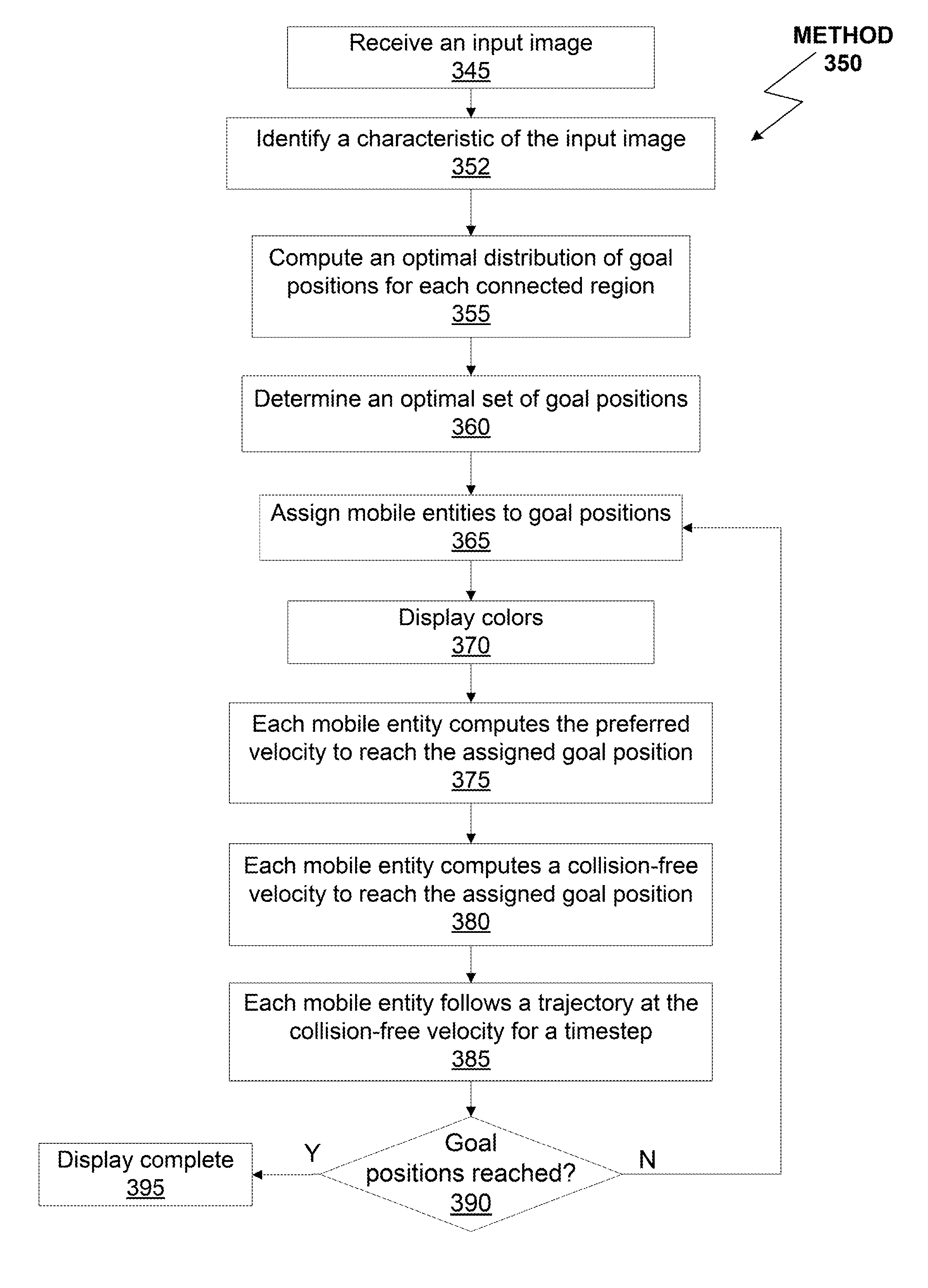
[0021]Embodiments of the invention include a system for reciprocal collision avoidance for multiple non-holonomic robots and choreographic multi-agent pattern formation. One embodiment of the present invention sets forth a method for controlling multiple non-holonomic robotic elements. The method comprises the steps of increasing a radius associated with each non-holonomic robotic element by a respective maximum tracking error value with respect to a trajectory of a holonomic robotic element to generate a set of modified radii and generating a set of collision-free velocities based on the set of modified radii, a first set of allowed holonomic velocities for each robotic element of multiple holonomic robotic elements, and a second set of collision-free velocities for each robotic element of the multiple holonomic robotic elements relative to neighboring robotic elements of the multiple holonomic robotic elements, where each robotic element of the multiple holonomic robotic elements ...


PUM


Abstract

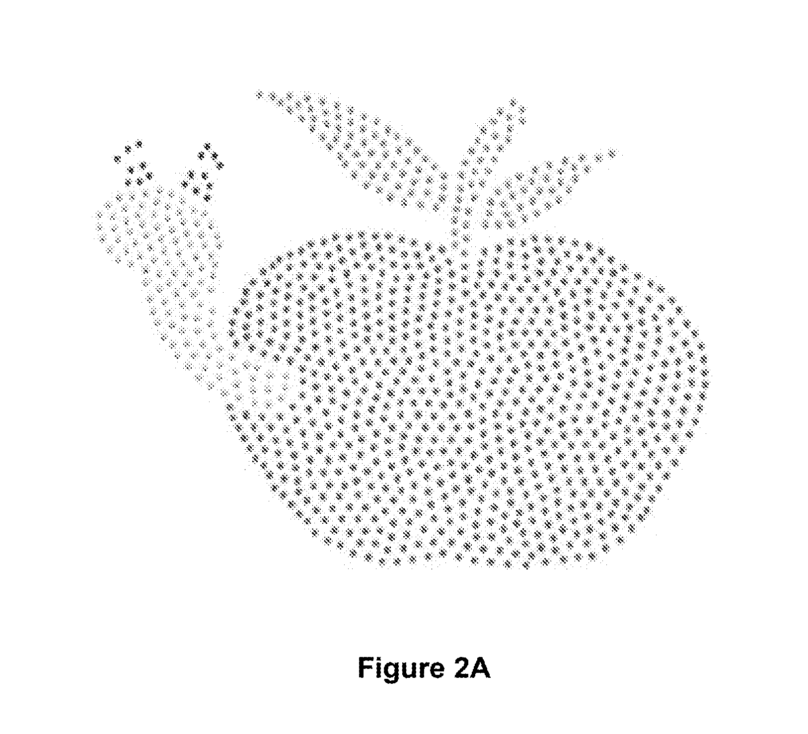
Techniques are disclosed for controlling robot pixels to display a visual representation of a real-world video texture. Mobile robots with controllable color may generate visual representations of the real-world video texture to create an effect like fire, sunlight on water, leaves fluttering in sunlight, a wheat field swaying in the wind, crowd flow in a busy city, and clouds in the sky. The robot pixels function as a display device for a given allocation of robot pixels. Techniques are also disclosed for distributed collision avoidance among multiple non-holonomic and holonomic robots to guarantee smooth and collision-free motions.

Description

CROSS-REFERENCE TO RELATED APPLICATIONS[0001]This application is a continuation in part of United States patent application titled, “A DISPLAY WITH ROBOTIC PIXELS,” filed on Jun. 8, 2011 and having Ser. No. 13 / 156,212 (Attorney Docket Number DISN / 0025) and claiming priority benefit to U.S. provisional patent application titled, “RECIPROCAL COLLISION AVOIDANCE FOR MULTIPLE NON-HOLONOMIC ROBOTS,” filed on Jul. 9, 2010 and having Ser. No. 61 / 363,154 (Attorney Docket Number DISN / 0025L.02) and U.S. provisional patent application titled, “CHOREOGRAPHIC MULTI-AGENT PATTERN FORMATION,” filed on Jun. 9, 2010 and having Ser. No. 61 / 353,179 (Attorney Docket Number DISN / 0025L). These related applications are also hereby incorporated by reference in their entirety.BACKGROUND[0002]1. Field of the Invention[0003]The present invention relates to the fields of robotics and visual displays and, in particular, to systems and methods for reciprocal collision avoidance for multiple non-holonomic robots ...

Claims


Application Information

Patent Timeline
IPC IPC(8): G06T11/40
CPCG06T11/001B25J9/1666
Inventor BEARDSLEY, PAULMORA, JAVIER ALONSOBREITENMOSER, ANDREASPERAZZI, FEDERICOHORNUNG, ALEXANDER
Owner ETH ZURICH EIDGENOESSISCHE TECHN HOCHSCHULE ZURICH
Learn More