Laser light shaping optical system

a laser light and optical system technology, applied in the field of laser light shaping optical systems, can solve the problems of increasing the number of parts or affecting the shape of the aspheric surface of the intensity conversion lens, and affecting the degree of freedom of optical design, so as to reduce the optical path length, prevent air breakdown, and reduce the effect of optical path length

Inactive Publication Date: 2012-08-16
HAMAMATSU PHOTONICS KK
View PDF8 Cites 7 Cited by
  • Summary
  • Abstract
  • Description
  • Claims
  • Application Information

AI Technical Summary

Benefits of technology

[0018]By contrast, the expansion / reduction optical system constituted by a pair of concave and convex lenses has no converging point (cross point) and thus can reduce the optical path length while preventing air breakdown from occurring at the converging point. Also, optical elements arranged within the expansion / reduction optical system, if any, are not damaged, which is advantageous in that the degree of freedom in optical design is high, whereby further smaller sizes can be achieved.
[0019]In a laser light shaping optical system which shapes an intensity distribution of laser light into a given intensity distribution, the present invention can inhibit the processing time for optical lenses from being prolonged by expanding or reducing the laser light.

Problems solved by technology

Arranging an expansion / reduction optical system behind the homogenizer as mentioned above may be problematic in that the number of parts or the optical path length increases.
However, new problems have occurred as follows.
That is, it complicates the form of the aspheric surface of the intensity conversion lens and increases the area of the intensity conversion lens and the difference in height of the aspheric surface.
As a result, the processing time required for manufacturing the intensity conversion lens becomes longer, thereby increasing the manufacturing cost and lowering the processing accuracy.
Also, this kind of intensity conversion lens may not be employed in existing optical systems with limited mounting spaces.

Method used


Image

  • Laser light shaping optical system
  • Laser light shaping optical system
  • Laser light shaping optical system

Examples


first embodiment

[0070]FIG. 12 is a structural diagram illustrating the laser light shaping optical system in accordance with the first embodiment of the present invention. This laser light shaping optical system 1 in accordance with the first embodiment comprises a homogenizer 10 constituted by a pair of aspherical lenses 11, 12 and an expansion optical system 20 disposed between the pair of aspherical lenses 11, 12.

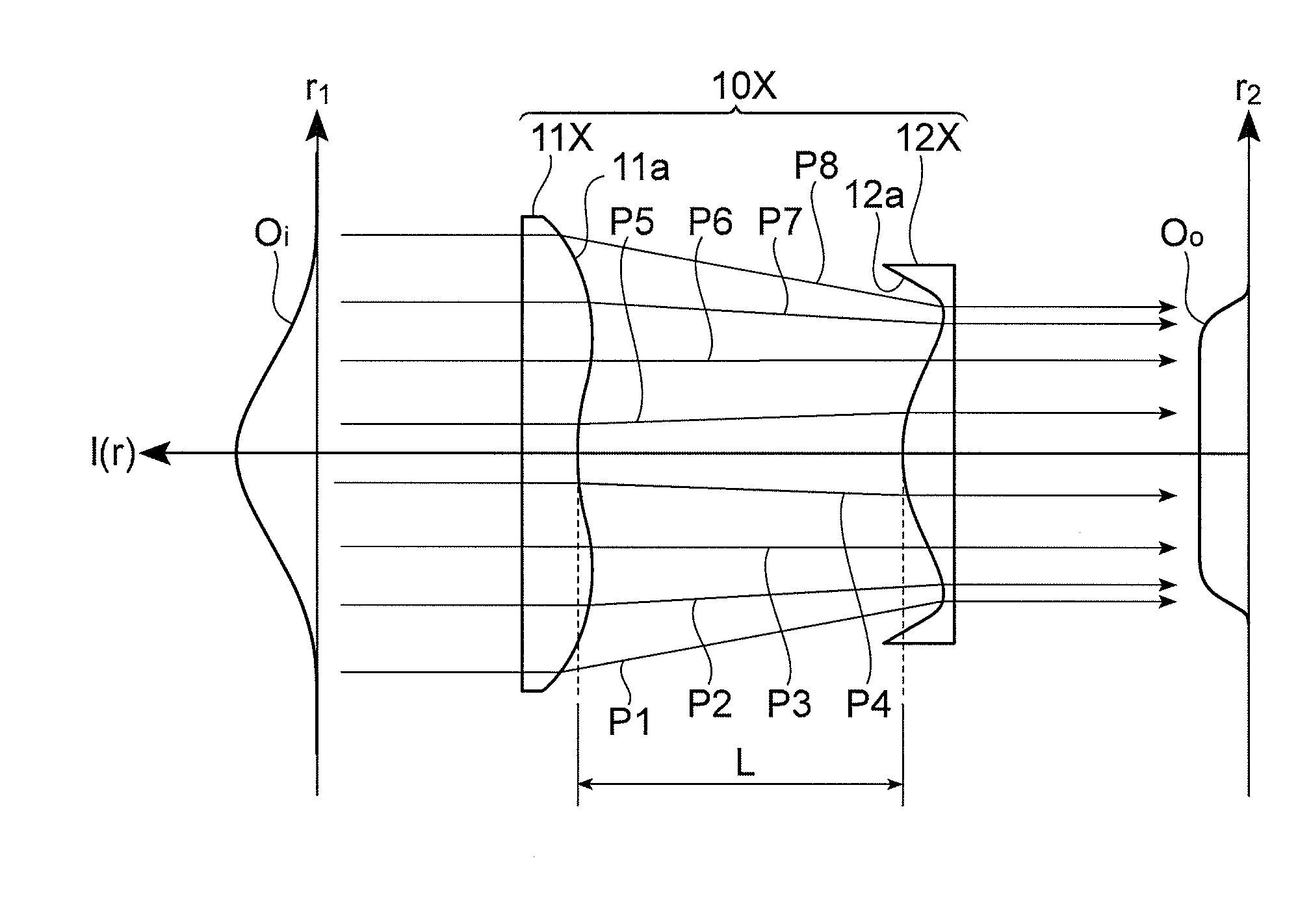
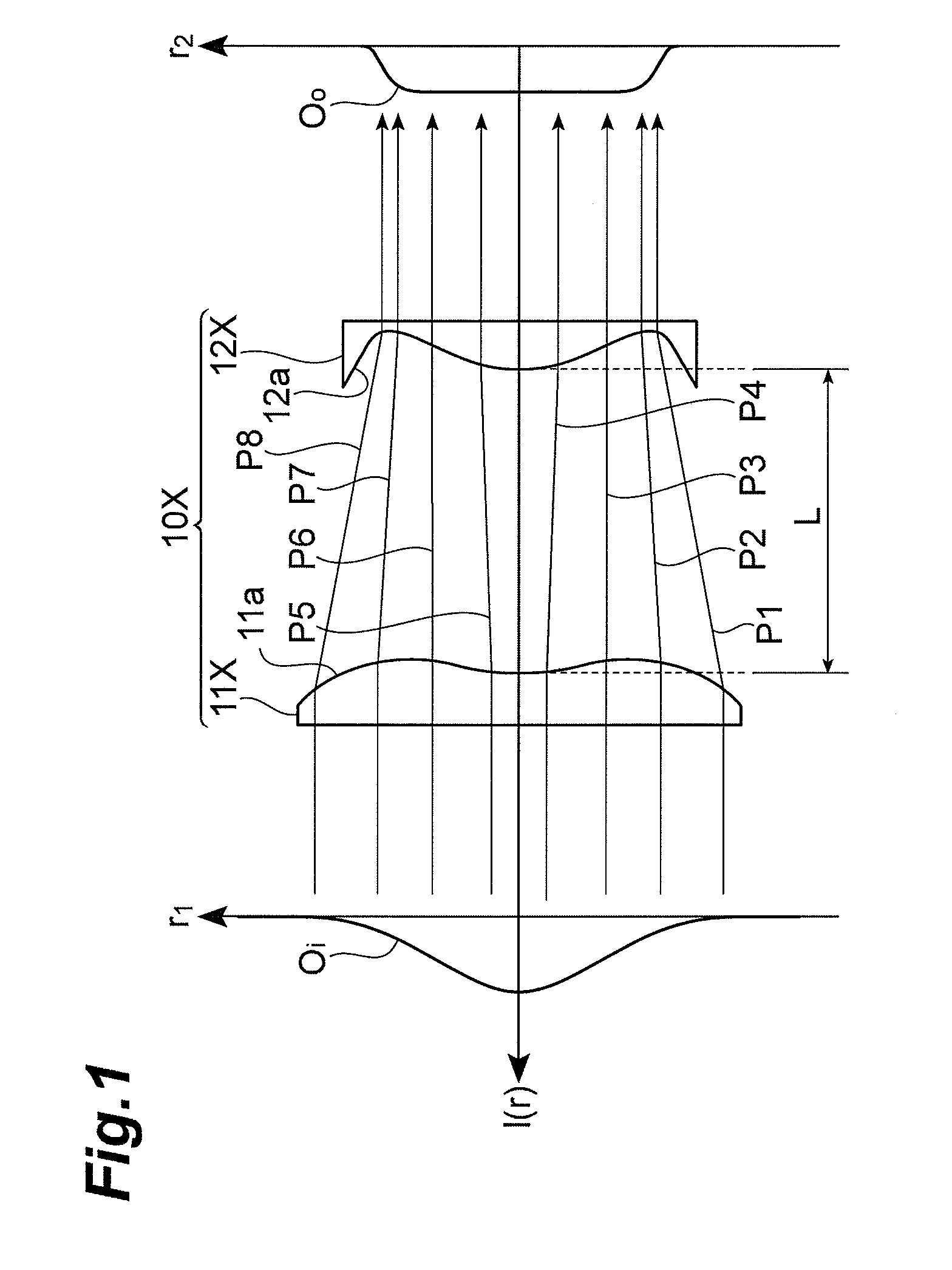
[0071]As with the above-mentioned homogenizer 10X, the homogenizer 10 is used for shaping an intensity distribution of laser light into a given form and comprises the pair of aspherical lenses 11, 12. The aspherical lens 11 on the entrance side functions as an intensity conversion lens for shaping the intensity distribution of the laser light into a given form as with the above-mentioned aspherical lens 11X. On the other hand, as with the above-mentioned aspherical lens 12X, the aspherical lens 12 on the exit side functions as a phase correction lens for homogenizing the phase of the sh...

first example

[0074]The laser light shaping optical system 1 in accordance with the first embodiment was designed as a first example. In the first example, as illustrated in FIG. 13, the laser light generated by a laser light source 30 was supposed to be expanded by an expander 40 and then made incident on the laser light shaping optical system 1.

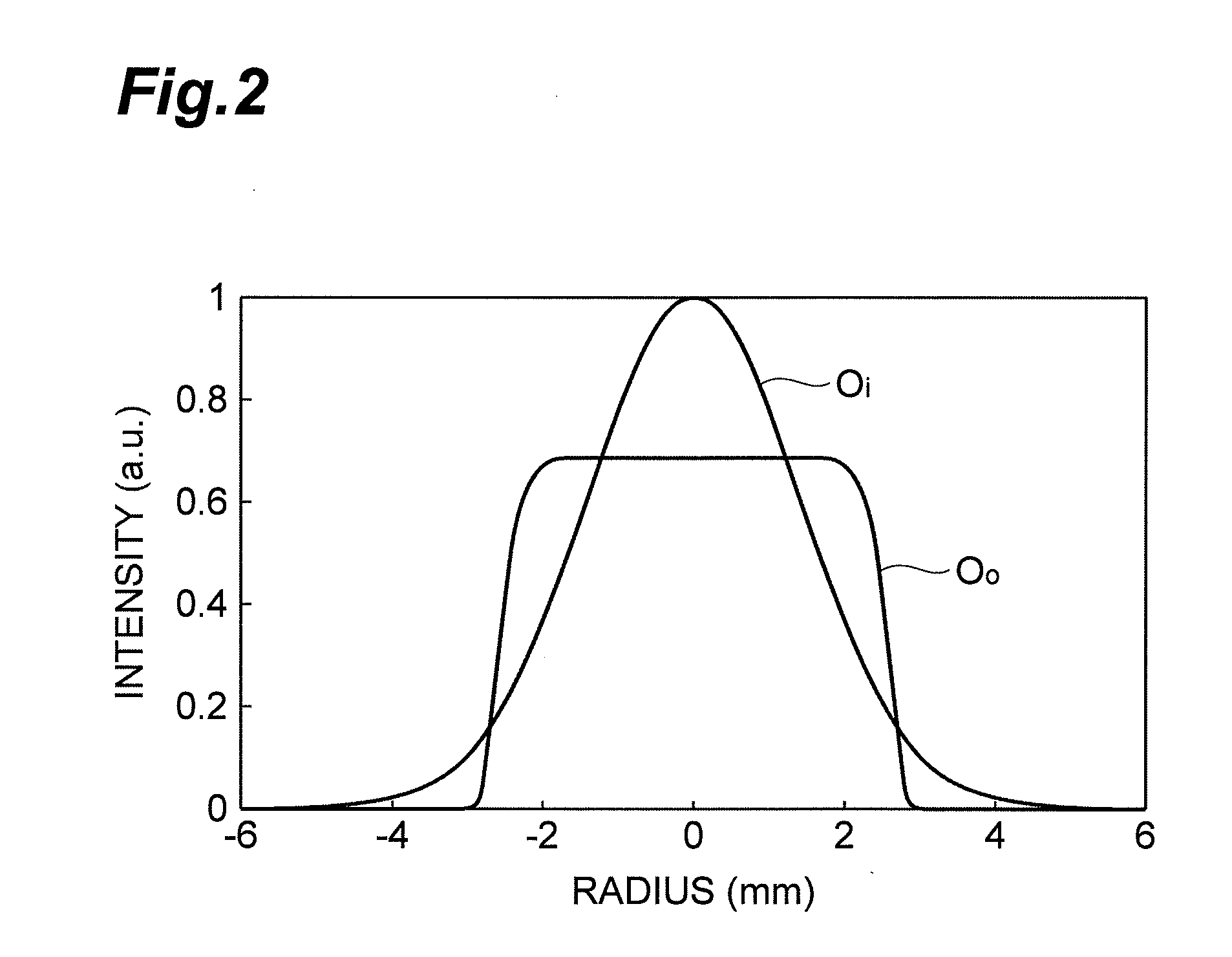
[0075]A fiber laser having a wavelength of 1064 nm was used as the laser light source 30, while employed as the expander 40 was one constituted by a pair of concave and convex lenses 41, 42. In this example, laser light Oi having expanded the laser light from the laser light source 30 to a diameter of 7.12 mm as illustrated in FIG. 14 was produced by the expander 40. According to FIG. 14, the intensity distribution of the laser light Oi incident on the laser light shaping optical system 1 was a concentric Gaussian distribution.

[0076]Then, as in the form design of the aspheric surface mentioned above, the form of the aspheric surface 11a of the intensity ...

second embodiment

[0086]FIG. 23 is a structural diagram illustrating the laser light shaping optical system in accordance with the second embodiment of the present invention. This laser light shaping optical system 1A in accordance with the second embodiment comprises a homogenizer 10A constituted by a pair of aspherical lenses 11A, 12A and an expansion optical system 20A disposed between the pair of aspherical lenses 11A, 12A.

[0087]As with the above-mentioned homogenizer 10, the homogenizer 10A is used for shaping an intensity distribution of laser light into a given form and comprises the pair of aspherical lenses 11A, 12A. The aspherical lens 11A on the entrance side functions as an intensity conversion lens for shaping the intensity distribution of the laser light into a given form as with the above-mentioned aspherical lens 11. On the other hand, as with the above-mentioned aspherical lens 12, the aspherical lens 12A on the exit side functions as a phase correction lens for homogenizing the phas...


PUM

PropertyMeasurementUnit
wavelengthaaaaaaaaaa
radiusaaaaaaaaaa
diameteraaaaaaaaaa

Abstract

A laser light shaping optical system 1 in accordance with an embodiment of the present invention comprises an intensity conversion lens 11 for converging and shaping an intensity distribution of laser light incident thereon into a desirable intensity distribution; a phase correction lens 12 for correcting the laser light emitted from the intensity conversion lens 11 into a plane wave by homogenizing a phase thereof; and an expansion/reduction optical system 20, arranged between the intensity conversion lens 11 and the phase correction lens 12, for expanding or reducing the laser light emitted from the intensity conversion lens 11.

Description

BACKGROUND OF THE INVENTION[0001]1. Field of the Invention[0002]The present invention relates to an optical system which shapes an intensity distribution of laser light into a given intensity distribution.[0003]2. Related Background Art[0004]Laser light typically has an intensity distribution which is the strongest near its center and gradually becomes weaker toward peripheries as in a Gaussian distribution. However, laser light having a spatially uniform intensity distribution has been desired for laser processing and the like.[0005]In this regard, Patent Literature 1 discloses, as a laser light shaping optical system for shaping an intensity distribution of laser light into a spatially uniform intensity distribution (e.g., a top-hat intensity distribution), one comprising an aspherical lens type homogenizer constituted by an intensity conversion lens and a phase correction lens. The laser light shaping optical system disclosed in Patent Literature 1 further comprises an image-form...

Claims


Application Information

Patent Timeline
Patent Type & Authority Applications(United States)
IPC IPC(8): F21V5/04G02B5/00G02B13/00G02B27/09
CPCB23K26/0648G02B27/0955G02B27/0927B23K26/0665
Inventor ITO, HARUYASUYASUDA, TAKASHI
Owner HAMAMATSU PHOTONICS KK
Why Eureka
Try Eureka