Off axis optical signal redirection architectures

a technology of optical signal redirection and optical path length, applied in optics, instruments, optical light guides, etc., can solve the problems of limited bandwidth and switching speed capabilities of oeo switches, and achieve the effects of reducing path length, reducing optical path length, and reducing effective packing density

Inactive Publication Date: 2005-09-13
NEOPHOTONICS CORP
View PDF39 Cites 4 Cited by
  • Summary
  • Abstract
  • Description
  • Claims
  • Application Information

AI Technical Summary

Benefits of technology

[0014]Optical signal redirection systems (e.g., OXCs, multiplexers, demultiplexers, optical protection switches, etc.) incorporating off axis reflective microstructure arrays in accordance with the present invention achieve a number of advantages. Greater effective packing density can be achieved by having the optical signal beams from the originating location(s) impinge on the reflective microstructure array at an angle. In fact, effective packing densities of virtually one-hundred percent can be achieved in one direction of the array. By having one of the entering or exiting beams impinge on the reflective microstructure array at an angle, originating and / or target location(s) may be placed in close proximity to the reflective microstructure array, thereby reducing the path length to / from the reflective microstructures. Reduced optical path length between system elements enables easier alignment and system assembly and also achieves reductions in optical signal losses, resulting in reduced cost and enhanced performance. Utilizing off axis reflective microstructure arrays enables greater flexibility regarding where optical ports, reflective microstructures, and other optical elements are positioned, enabling greater flexibility in overall system designs. Off axis optical signal redirection system architectures inherently enable the use of high tilt angle reflective microstructure positioning systems, further enabling shorter path lengths, easier alignment, reduced signal loss, and greater flexibility in system design. Further, the high tilt angle reflective microstructure positioning systems may be designed to only require two control signals for operation. Minimizing the number of required control signals is advantageous for several reasons: (1) it enables greater real reflective microstructure packing density for large arrays because of the reduced number of on-chip interconnects; (2) it enables simpler packaging methods because of the reduced number of off-chip interconnects; (3) it enables simpler control systems because of the reduced number of control signals; and (4) it enables the entire optical system to be inherently more reliable because of the reduced number of interconnects and components.

Problems solved by technology

As may be appreciated, the bandwidth and switching speed capabilities of an OEO switch may be limited by the initial optical-to-electrical and subsequent electrical-to-optical signal conversions that are required.

Method used


Image

  • Off axis optical signal redirection architectures
  • Off axis optical signal redirection architectures
  • Off axis optical signal redirection architectures

Examples


Embodiment Construction

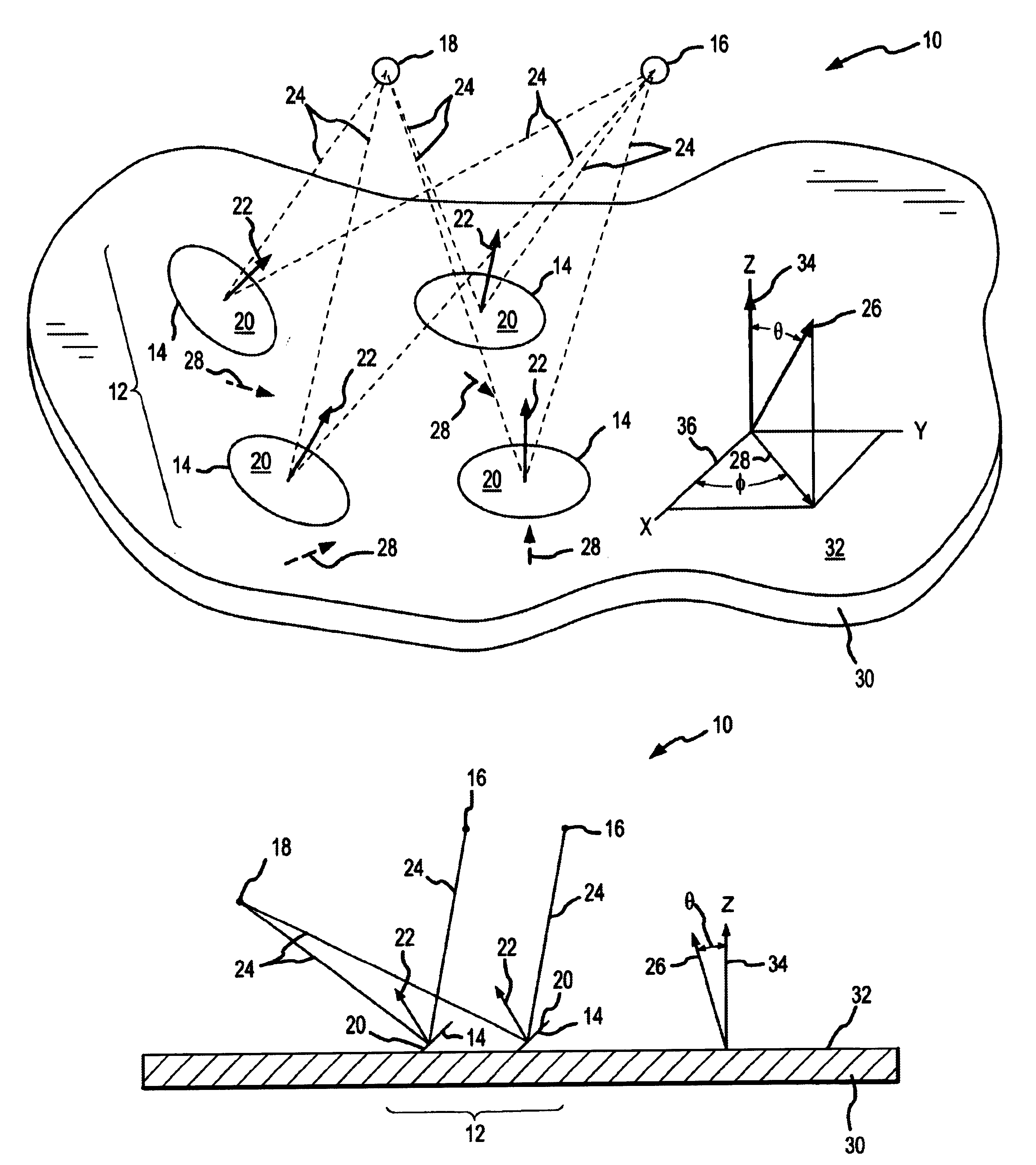
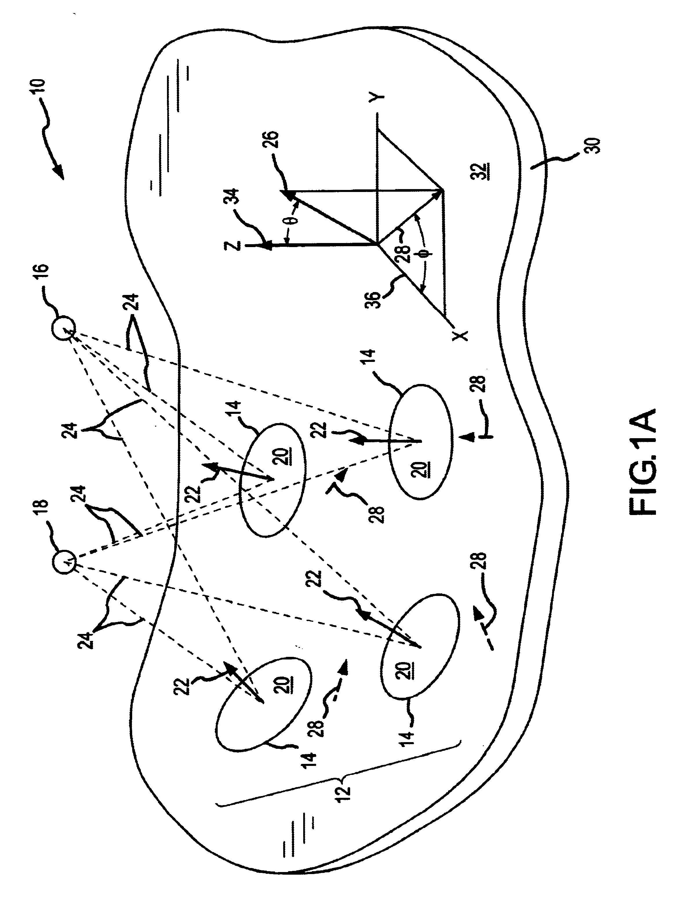
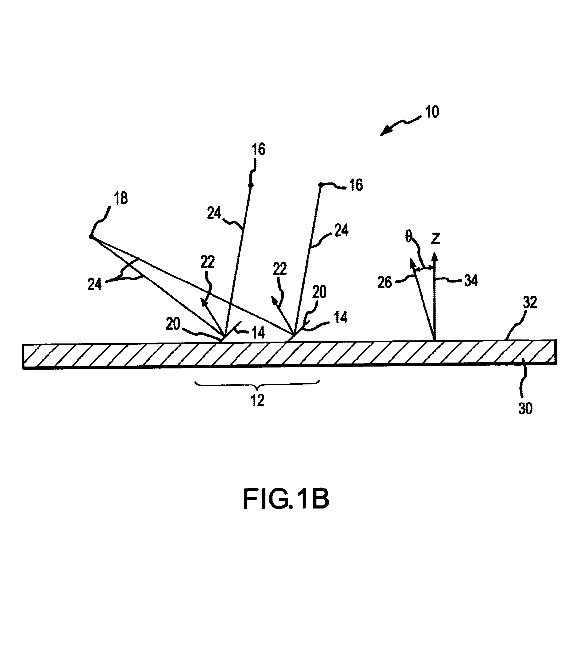
[0035]Referring now to FIGS. 1A-C, there are shown several examples of off axis optical signal redirection systems 10. The optical signal redirection systems 10 shown include one reflective microstructure array 12 formed on a single substrate 30. However, in other embodiments, there may be two or more reflective microstructure arrays 12 formed on one, two or more substrates 30. Each reflective microstructure array 12 includes one or more reflective microstructures 14. Each of the reflective microstructures 14 includes an optically reflective surface 20 and is positionable with respect to the substrate 30 in order to orient its reflective surface 20 for redirecting optical signals 24 incoming from one or more originating locations 16 to one or more target locations 18. It will be appreciated that, depending upon the direction of propagation of the optical signals 24, an originating location 16 may be a target location 18 and a target location 18 may be an originating location 16. For...


PUM


Abstract

The present invention is directed to off axis optical signal redirection architectures that employ positionable reflective microstructures (e.g. microelectromechanical (MEM) mirrors) fabricated on one or more substrates. In one embodiment, an optical signal redirection system (10) includes a reflective microstructure array (12) formed on a substrate (30). The reflective microstructure array (12) includes one or more reflective microstructures (14). Each of the reflective microstructures (14) includes an optically reflective surface (20) and is positionable with respect to the substrate (30) in order to orient its reflective surface (20) for redirecting optical signals (24) incoming from one or more originating locations (16) to one or more target locations (18). Each orientation required for a given reflective microstructure (14) to redirect an optical signal (24) incoming from an originating location (16) to a target location (18) is defined by a unit vector (22) that is normal to the reflective surface (20) of such reflective microstructure (14). An average normal vector (26) associated with the reflective microstructure array (12) defined as the average of the set of individual unit normal vectors (22) forms a first non-zero angle θ with respect to the substrate normal (34).

Description

FIELD OF THE INVENTION[0001]The present invention relates generally to the field of optical telecommunications equipment, and more particularly to reflective-type optical signal redirection equipment employing one or more arrays of positionable reflectors.BACKGROUND OF THE INVENTION[0002]With the increasing use of optical signals in telecommunications networks, the demand for high-bandwidth capable equipment for redirecting the transmission of optical signals within the network, such as N×N optical switches (where N is a positive whole number), multiplexers (i.e. an N×1 switch), demulitplexers (i.e., a 1×N switch) and the like, has increased. One type of optical switch converts an optical signal received on one optical port to the switch interface (e.g., an optical fiber end) to an electrical signal, redirects the signal electronically, and re-converts the electrical signal to an optical signal output on a desired optical port from the switch interface (e.g., another optical fiber e...

Claims


Application Information

Patent Timeline
Patent Type & Authority Patents(United States)
IPC IPC(8): G02B6/35G02B6/42
CPCG02B6/3556G02B6/3512G02B6/4214G02B6/4249B33Y80/00
Inventor MILLER, SAMUEL LEEMCWHORTER, PAUL JACKSON
Owner NEOPHOTONICS CORP
Why Eureka
Try Eureka