Catoptric imaging systems comprising pellicle and/or aperture-array beam-splitters and non-adaptive and/or adaptive catoptric surfaces
Inactive Publication Date: 2006-03-30
ZETETIC INST
View PDF67 Cites 5 Cited by
Summary
Abstract
Description
Claims
Application Information
AI Technical Summary
This helps you quickly interpret patents by identifying the three key elements:
Problems solved by technology
Method used
Benefits of technology
[0044] Another advantage of at least one embodiment of the present invention is differential measurements of spatial Fourier components of a plane section embedded in a substrate.
[0045] Another advantage of at least one embodiment of the present invention is high speed lateral differential interferometric scans of an embedded plane section of a substrate.
[0046] Another advantage of at least one embodiment of the present invention is the use of high speed N-dimensional bi- and quad-homodyne detection methods.
[0047] Another advantage of at least one embodiment of
Problems solved by technology
The increase in intensity of desired images and the reduction of statistical errors lead to an increase in signal-to-noise ratios and to a concomitant increase in throughput of a metrology tool using the catoptric imaging system.
In the case where a beam-splitter is u
Method used
Image
Click on the blue label to locate the original text in one second.
Reading with bidirectional positioning of images and text.
Examples
Embodiment Construction
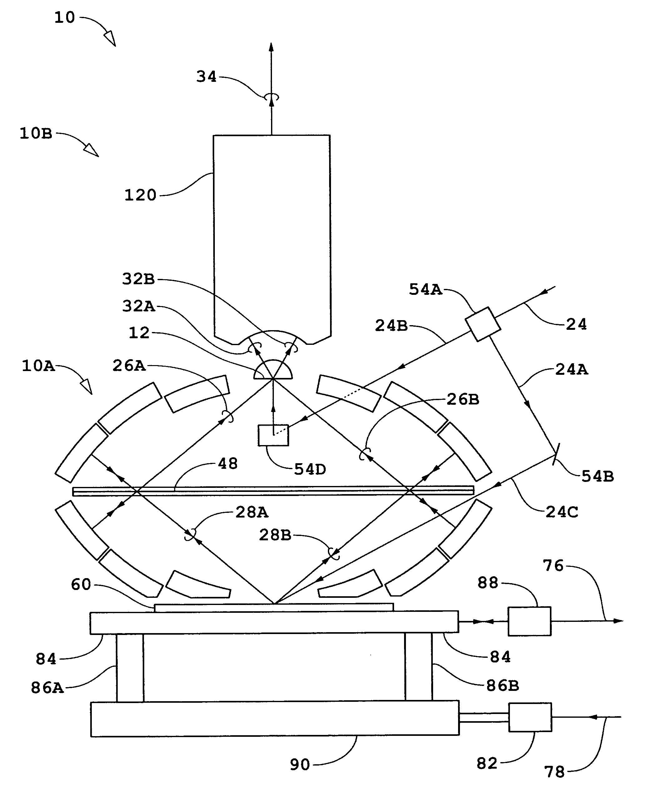
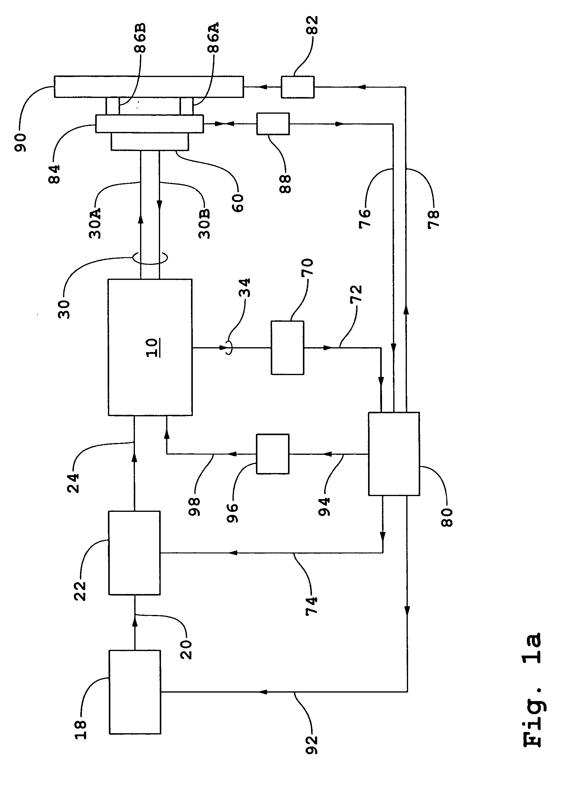
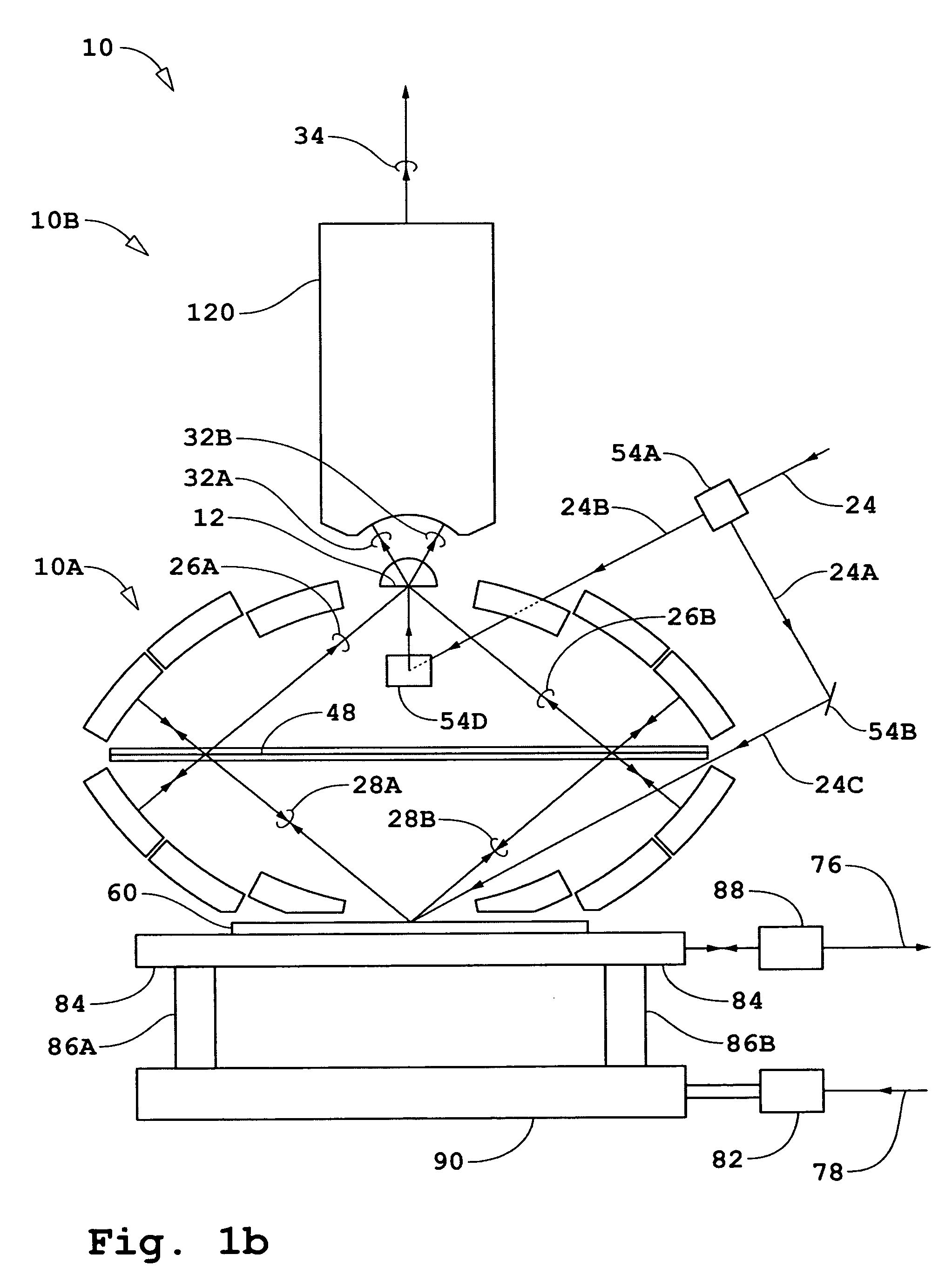
[0072] A general description of embodiments incorporating the present invention will first be given for interferometer systems wherein either a N-dimensional bi- or quad-homodyne detection method is used where N is an integer. Referring to FIG. 1a, an interferometer system is shown diagrammatically comprising an interferometer 10, a source 18, a beam-conditioner 22, a detector 70, an electronic processor and controller 80, and a measurement object shown as substrate 60. Source 18 generates input beam 20. The interferometer system shown in FIG. 1a is for the case of an imaging system operating in a reflecting mode to measure properties of fields reflected / scattered by substrate 60. For the case of operation in a transmission mode, a portion of beam 24 split off as a measurement beam is incident on substrate 60 from the backside of substrate 60 such as shown diagrammatically in FIG. 2a. Source 18 is preferably a pulsed source that generates beam 20 with a single frequency component. B...
PUM
Abstract
An interferometry system including: a first imaging system that directs a measurement beam at an object to produce a return measurement beam from the object, that directs the return measurement beam onto an image plane, and that delivers a reference beam to the image plane; and a beam combining element in the image plane, said beam combining element comprising a first layer containing an array of sagittal slits and a second layer containing an array of tangential slits, wherein each slit of the array of sagittal slits is aligned with a corresponding different slit of the array of tangential slits, wherein the beam combining element combines the return measurement beam with the reference beam to produce an array of interference beams.
Description
[0001] This application also claims the benefit of U.S. Provisional Application No. 60 / 611,564, filed Sep. 20, 2004, incorporated herein by reference. RELATED APPLICATIONS [0002] The following applications are related to the present application: U.S. Pat. No. 6,552,852, issued Apr. 22, 2003 and entitled “Catoptric and Catadioptric Imaging Systems,” (ZI-38); U.S. Ser. No. 60 / 447,254, filed Feb. 13, 2003, and U.S. Ser. No. 10 / 778,371, filed Feb. 13, 2004, both of which are entitled “Transverse Differential Interferometric Confocal Microscopy,” (ZI-40); U.S. Ser. No. 60 / 448,360, filed Feb. 19, 2003, and U.S. Ser. No. 10 / 782,057, filed Feb. 19, 2004, both of which are entitled “Longitudinal Differential Interferometric Confocal Microscopy For Surface Profiling,” (ZI-41); U.S. Ser. No. 60 / 448,250, filed Feb. 19, 2003, and U.S. Ser. No. 10 / 782,058, filed Feb. 19, 2004, both of which are entitled “Method And Apparatus For Dark Field Interferometric Confocal Microscopy,” (ZI-42); U.S. Pat. ...
Claims
Application Information
Patent Timeline
Application Date:The date an application was filed.
Publication Date:The date a patent or application was officially published.
First Publication Date:The earliest publication date of a patent with the same application number.
Issue Date:Publication date of the patent grant document.
PCT Entry Date:The Entry date of PCT National Phase.
Estimated Expiry Date:The statutory expiry date of a patent right according to the Patent Law, and it is the longest term of protection that the patent right can achieve without the termination of the patent right due to other reasons(Term extension factor has been taken into account ).
Invalid Date:Actual expiry date is based on effective date or publication date of legal transaction data of invalid patent.