
Test phantom for tomographic imaging and notably for breast tomosynthesis

Inactive Publication Date: 2012-08-16
GENERAL ELECTRIC CO
View PDF0 Cites 8 Cited by
  • Summary
  • Abstract
  • Description
  • Claims
  • Application Information

AI Technical Summary

Benefits of technology

[0014]In accordance with another embodiment of the present invention, there is provided a method for tomographic imaging, the method comprises acquiring tomography or tomosynthesis images of a test phantom, the phantom comprising an assembly of elementary structures defining a 3D mesh, wherein each elementary structure comprises a chief constituent material corresponding to an X-ray attenuation

Problems solved by technology

Methods for the digital processing of images have been proposed in this respect, but are not yet fully satisfactory.
In particular, the methods only allow binary classification between dense tissue and fatty tissue, but fail to give full satisfaction.
For mammography, in particular, the low number of acquired projections and limited angle views can lead to bias with respect to voxel values which, for practitioners, does not contribute to facilitating evaluation of the glandularity of mammary tissue in available images.

Method used


Image

  • Test phantom for tomographic imaging and notably for breast tomosynthesis
  • Test phantom for tomographic imaging and notably for breast tomosynthesis
  • Test phantom for tomographic imaging and notably for breast tomosynthesis

Examples


Embodiment Construction

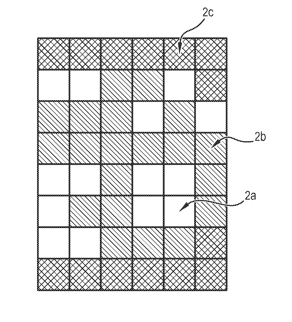
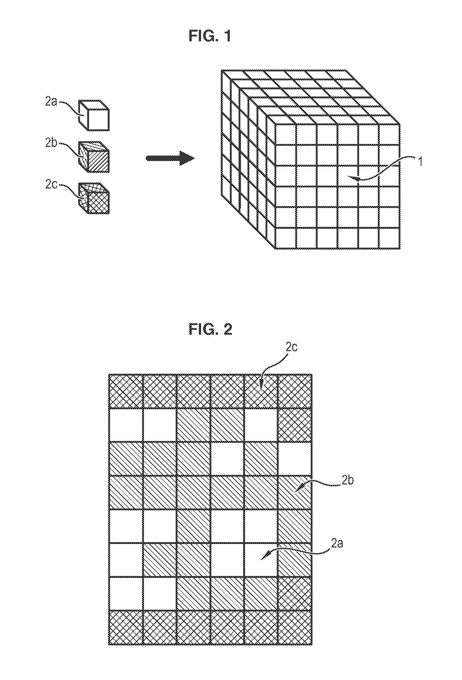
[0019]A test phantom 1 is illustrated in FIG. 1. In one embodiment, the test phantom 1 is a 3D structure, parallelepiped, and formed from elementary structures 2a, 2b, 2c. As used herein, the term “elementary structures” is intended to be representative of any elements which can be assembled to form a 3D meshing of a volume.

[0020]In the embodiment illustrated in FIG. 1, the elementary structures 2a, 2b, 2c are elementary cubes which are assembled one on another to form the parallelepiped 1.

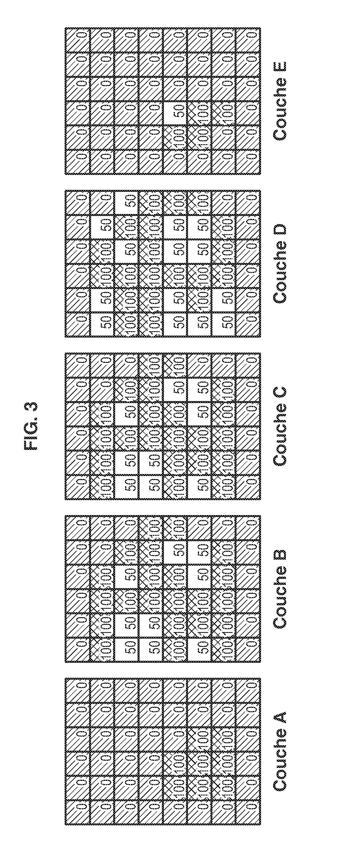
[0021]These elementary cubes 2a, 2b, 2c can be of several different types, wherein each type corresponds to a different chief constituent material. Test phantoms made from elementary structures corresponding to only two types of constituent material can be envisaged. Test phantoms made from elementary structures corresponding to three or more types of constituent materials are also possible.

[0022]These different types of constituent materials correspond to different X-ray attenuations and simulate...


PUM


Abstract

A test phantom for tomographic imaging, the phantom comprising an assembly of elementary structures defining a 3D mesh, wherein each elementary structure comprises a chief constituent material corresponding to an X-ray attenuation simulating a glandularity, wherein the elementary structures are in at least two types of chief constituent materials corresponding to different X-ray attenuations.

Description

BACKGROUND OF THE INVENTION[0001]1. Field of the Invention[0002]Embodiments of the present invention relate to a test phantom for tomographic imaging. More particularly, embodiments of the present invention may be applied to breast tomosynthesis.[0003]2. Description of the Prior Art[0004]For many years it has been known, especially in mammography, to use test phantoms for testing performance levels of equipment. In one particular example, these test objects are in the form of a supporting structure on which a test slab in wax is placed, small structures are embedded in the test objects to model, for example, micro-calcifications, fibrous structures or tumours.[0005]These test phantoms, for example those marketed by CIRS (CIRS 015) or Gammex (Gammex 156), are given particular use under the ACR accreditation program (“American College of Radiology”).[0006]Test phantoms are also known to be used in mammography to calibrate or evaluate artefacts, and are in the form of fully homogeneous...

Claims


Application Information

Patent Timeline
IPC IPC(8): G01D18/00
CPCA61B6/583A61B5/4872A61B6/025A61B6/502
Inventor MULLER, SERGEVANCAMBERG, LAURENCEIORDACHE, RAZVANKLAUSZ, REMY
Owner GENERAL ELECTRIC CO
Learn More