Intervertebral cage and implanting apparatus and operating method thereof

Inactive Publication Date: 2012-08-16
WILTROM
View PDF4 Cites 74 Cited by
  • Summary
  • Abstract
  • Description
  • Claims
  • Application Information

AI Technical Summary

Benefits of technology

[0008]The disclosure is directed to an intervertebral cage, an implanting apparatus and an operating method thereof. The coupling column and the sleeve of the implanting apparatus clamp the inte

Problems solved by technology

However, the intervertebral discs having been pressed by local stresses over a long period of time tend to degenerate or even become herniated so as to suppress the nerves.
Thus, degenerated or herniated intervertebral discs would cause acute pain and such pain is hard to relieve.
Also, in terms of uniform di

Method used


Image

  • Intervertebral cage and implanting apparatus and operating method thereof
  • Intervertebral cage and implanting apparatus and operating method thereof
  • Intervertebral cage and implanting apparatus and operating method thereof

Examples


Embodiment Construction

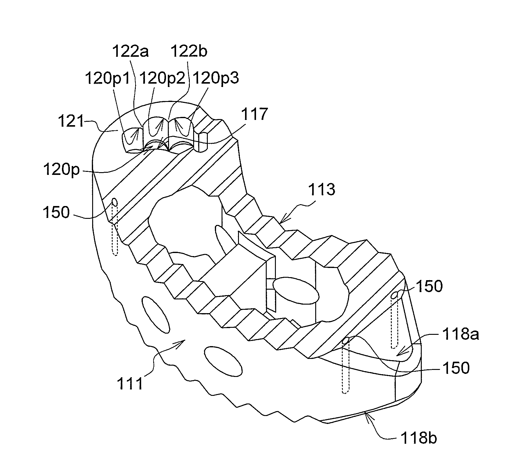
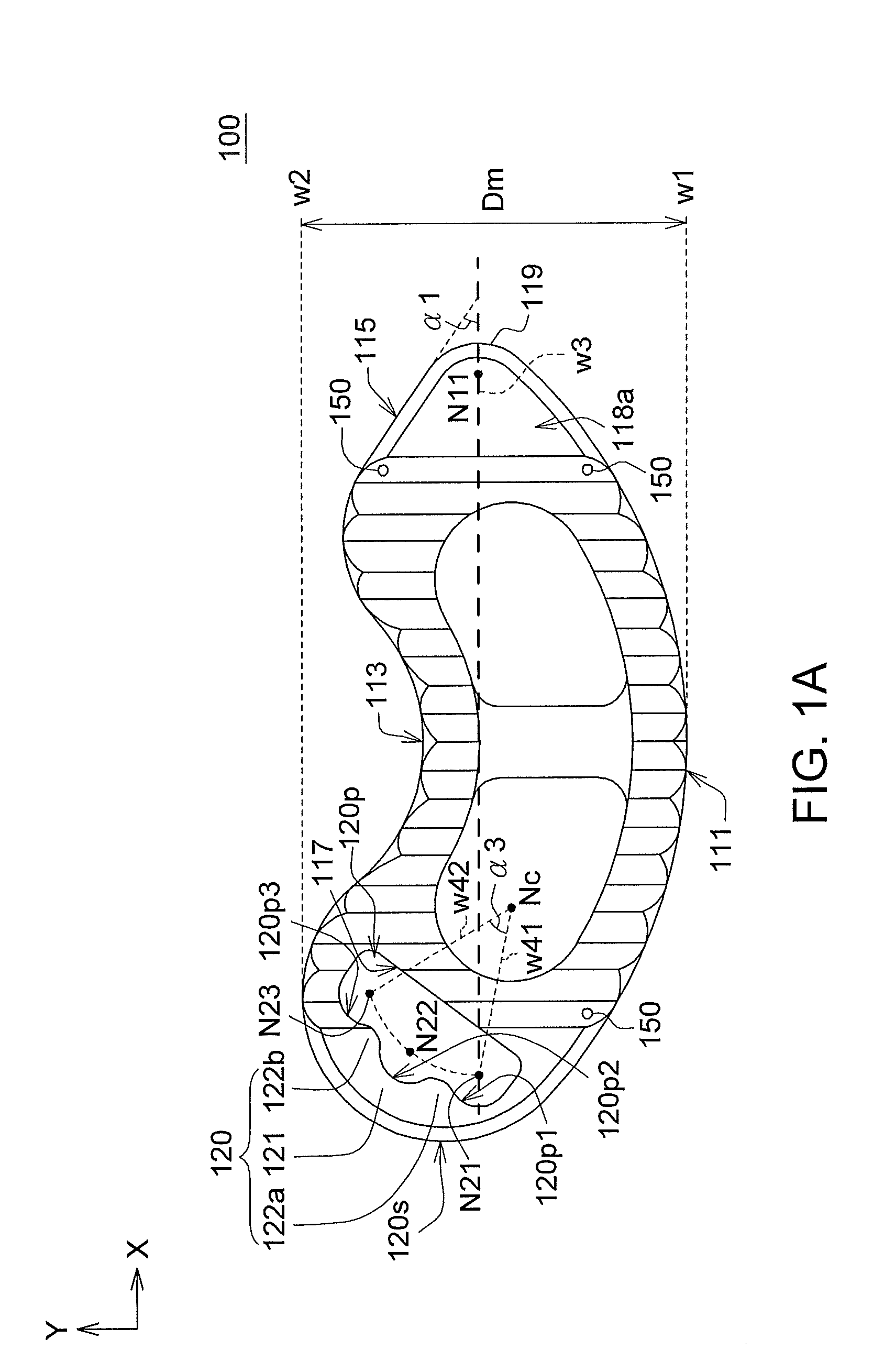
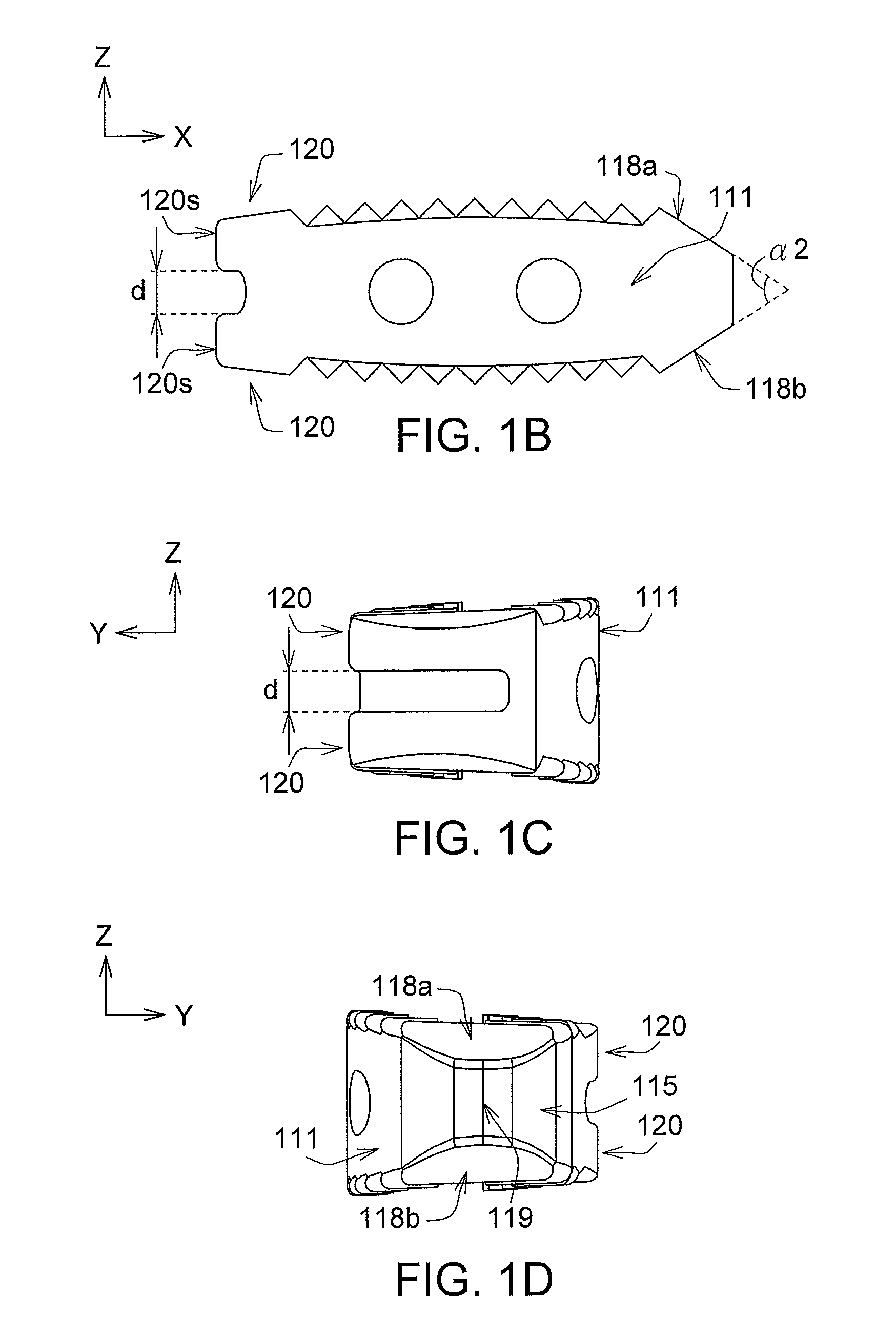
[0020]Firstly, the structures of an intervertebral cage 100 (as indicated in FIGS. 1A˜1G) and an implanting apparatus 200 (as indicated in FIGS. 2A and 2B) of the present embodiment of the disclosure are disclosed. Next, processes of clamping the intervertebral cage 100 by the implanting apparatus 200 are elaborated with accompanying drawings FIGS. 3A˜3C. Lastly, processes of implanting the intervertebral cage 100 into a location between two adjacent vertebral bodies by the implanting apparatus 200 are elaborated with accompanying drawings FIGS. 4A˜4F

[0021]Referring to FIGS. 1A˜1G, diagrams respectively showing the intervertebral cage 100 viewed from different view angles according to an embodiment of the disclosure are shown in FIGS. 1A˜1D, 3-D diagrams of the intervertebral cage 100 of FIGS. 1A˜1D viewed from different view angles are respectively shown in FIGS. 1E and 1F, and the intervertebral cage 100 of FIG. 1A designated with length L and width D is shown in FIG. 1G. The inte...


PUM


Abstract

An intervertebral cage, an implanting apparatus and an operating method thereof are provided. The intervertebral cage for being implanted between two adjacent vertebral bodies includes a body and a connecting portion. The body has a lateral convex surface, an inclined surface, a lateral concave surface and a connecting surface connected sequentially. The connecting portion includes a main portion and a protrusion. The main portion connected to the connecting surface has a through hole. The protrusion is protruded from the main portion into the through hole to form first and second inner arc surfaces. The maximum width of the intervertebral cage is a distance between first and second lines. The first and second lines are substantially parallel to a tangent line of the lateral convex surface and the first line, respectively. The distance between the inclined surface and the first line decreases gradually along a direction away from the connecting portion.

Description


Claims


Application Information

Patent Timeline
Owner WILTROM
Why Eureka
Try Eureka