
Designing task execution order based on location of the task icons within a graphical user interface

a task execution and task technology, applied in the direction of source code creation, program control, instruments, etc., can solve the problems of application failure to initiate, application background services cannot be included in the default startup, connection client failure,

Inactive Publication Date: 2012-08-16
IBM CORP
View PDF6 Cites 94 Cited by
  • Summary
  • Abstract
  • Description
  • Claims
  • Application Information

AI Technical Summary

Benefits of technology

[0009]For example, in an embodiment, different rows of the grid pattern may be located at different heights in the view. All the tasks represented by task icons in the same row are e

Problems solved by technology

Because certain applications have prerequisite background services which must be started up before the applications can initiate, these applications requiring the background services cannot be included in the default Startup folder, and must be manually initiated after the required background services are available.
These applications will fail to initiate unless a connection has been previously made to access the Internet, and that connection client may also fail if particular network services have not yet been established.
Full-featured workflow management software exists, such as i2 Corporation's Informatica tool, but these require extremely complicated setup configurations, including identifying a specific fixed logical link between parent and child tasks.
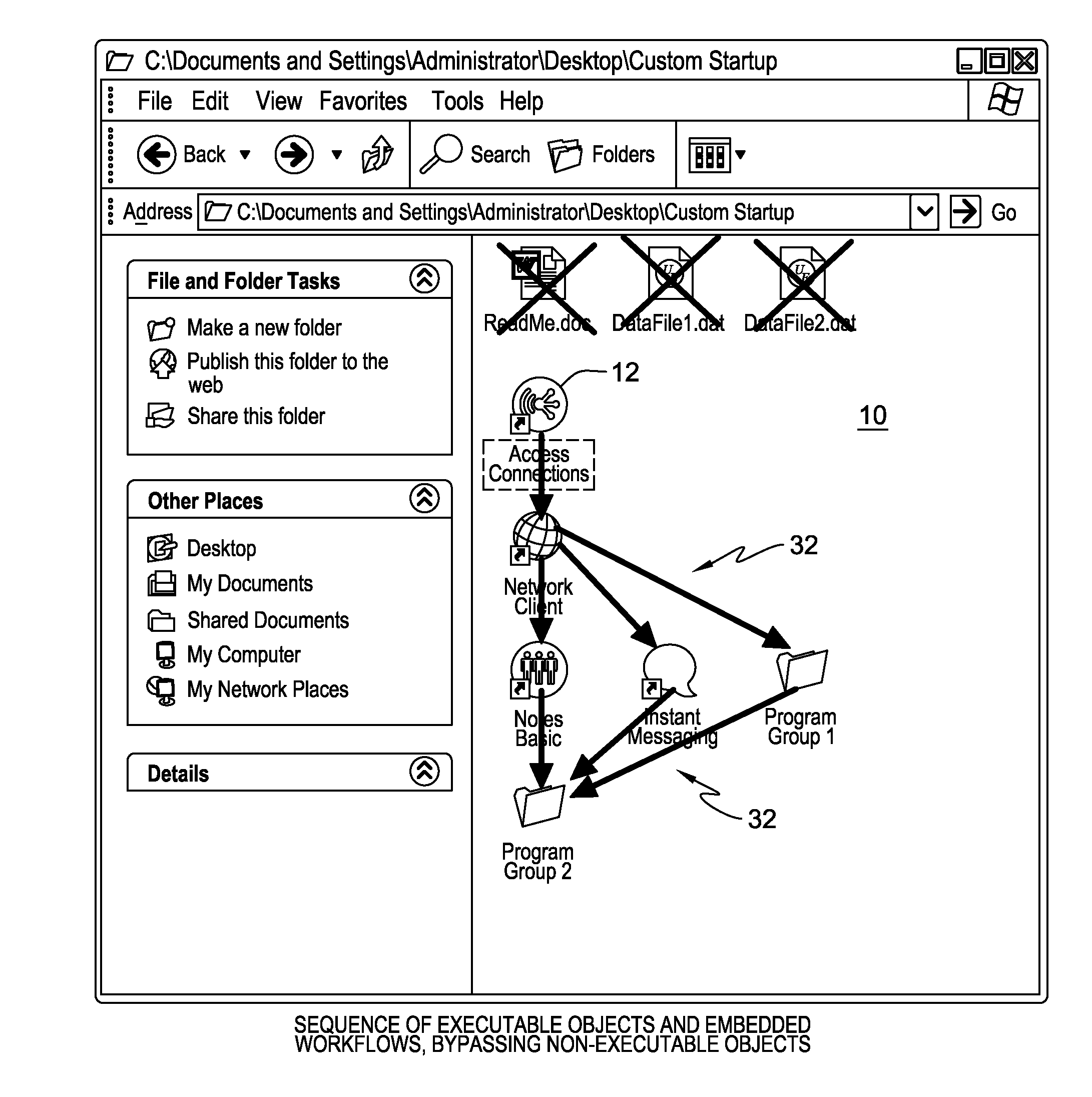
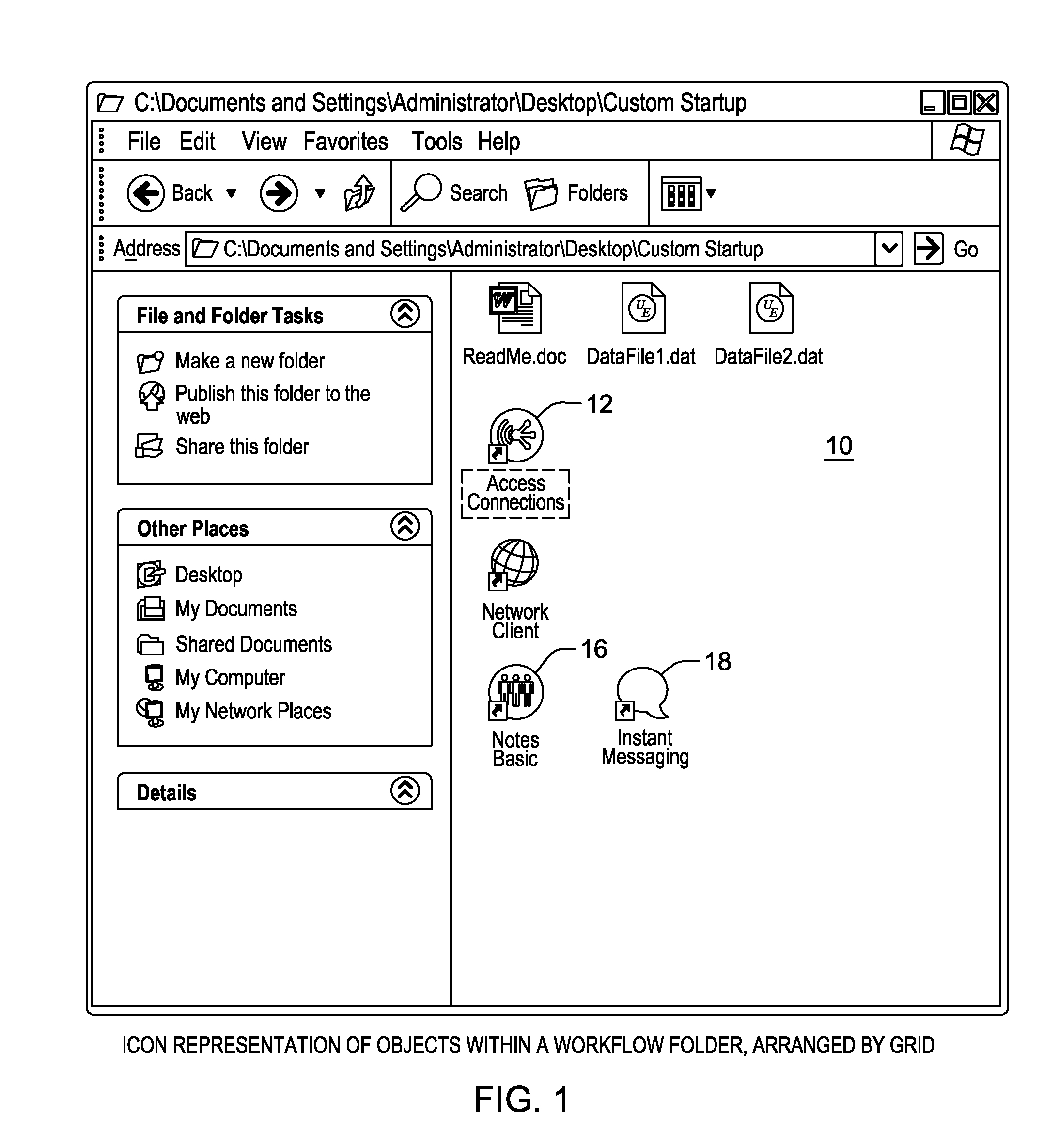
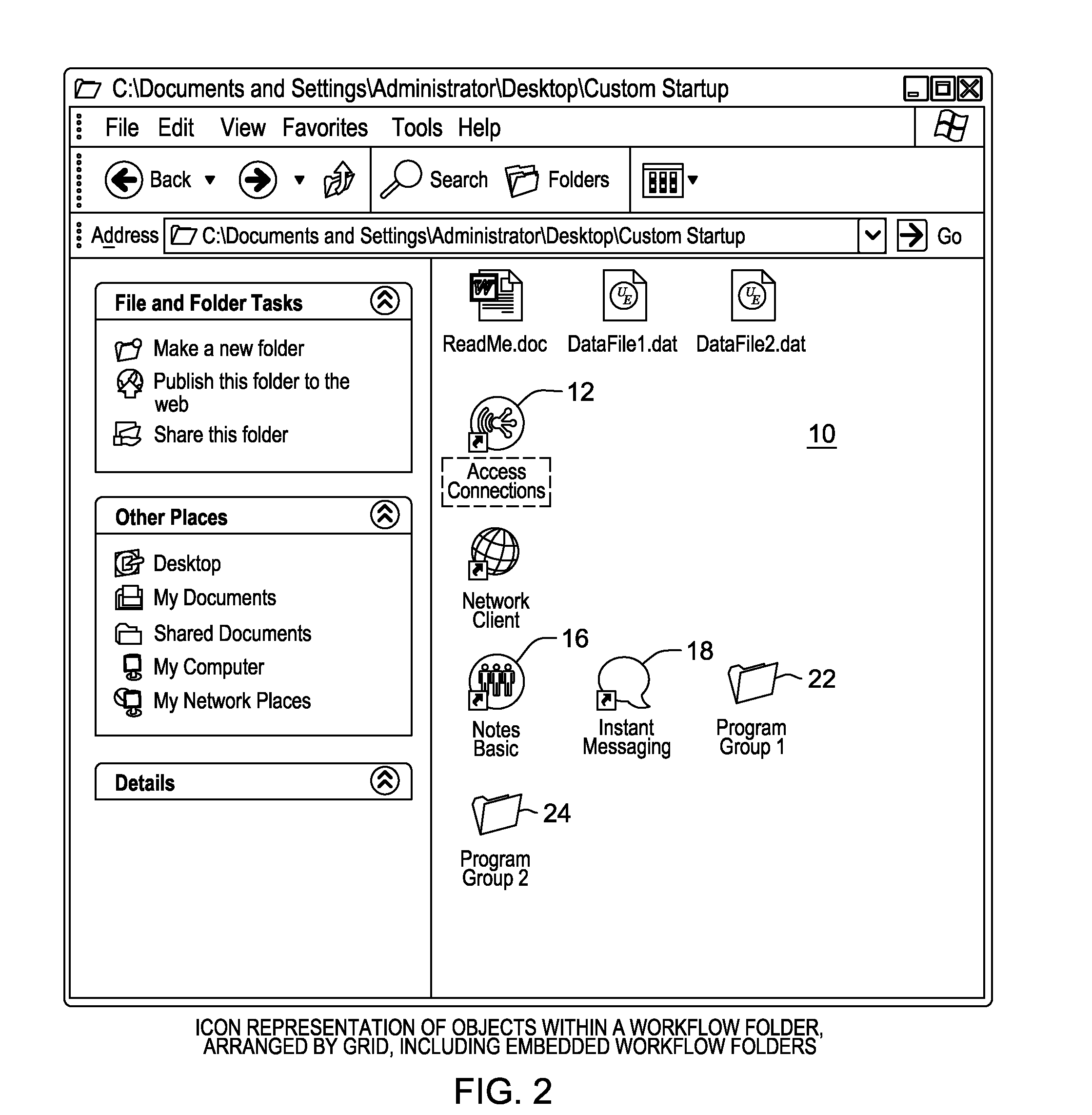
No solution currently exists in which the execution sequence of tasks within a folder can be identified more simply and efficiently by the geometric location of the icons in the GUI representation.

Method used


Image

  • Designing task execution order based on location of the task icons within a graphical user interface
  • Designing task execution order based on location of the task icons within a graphical user interface
  • Designing task execution order based on location of the task icons within a graphical user interface

Examples


Embodiment Construction

[0022]As will be appreciated by one skilled in the art, embodiments of the present invention may be embodied as a system, method or computer program product. Accordingly, embodiments of the present invention may take the form of an entirely hardware embodiment, an entirely software embodiment (including firmware, resident software, micro-code, etc.) or an embodiment combining software and hardware aspects that may all generally be referred to herein as a “circuit,”“module” or “system.” Furthermore, embodiments of the present invention may take the form of a computer program product embodied in any tangible medium of expression having computer usable program code embodied in the medium.

[0023]Any combination of one or more computer usable or computer readable medium(s) may be utilized. The computer-usable or computer-readable medium may be, for example but not limited to, an electronic, magnetic, optical, electromagnetic, infrared, or semiconductor system, apparatus, device, or propag...


PUM


Abstract

A method, system and computer program product for designating the order in which a plurality of tasks are to be executed on a computer system. In one embodiment, a plurality of task icons, each of which represents a respective one task, are shown in defined positions in a view on the computer system, and these defined positions of the task icons are used to determine the order in which the tasks are to be executed by the computer system. In an embodiment, the task icons are shown in a grid pattern, having rows and columns. Tasks represented by task icons shown in successive rows of the grid pattern are executed in series, and tasks represented by task icons shown in the same row of the grid pattern are executed in parallel. In an embodiment, at least one of the task icons represents an embedded executable workflow folder.

Description

BACKGROUND OF THE INVENTION[0001]This invention generally relates to determining the order in which to execute tasks in a computer system, and more specifically, to using a graphical user interface to determine that order.[0002]Desktop graphical user interfaces (GUI) in most common workstation operating systems provide views of folder content in several different formats, including the placement of large icons representing objects contained in the folder. For example, one system folder used in the Windows Operating System contains applications to be initiated or executable tasks to be processed during workstation bootup operations. These applications and tasks are typically initiated in an unspecified sequence, executing in parallel until all are completed. Because certain applications have prerequisite background services which must be started up before the applications can initiate, these applications requiring the background services cannot be included in the default Startup fold...

Claims


Application Information

Patent Timeline
IPC IPC(8): G06F3/048
CPCG06F8/34G06F3/04817G06F3/0482G06F9/5038
Inventor DELIA, WAYNE M.TENER, STUART B.
Owner IBM CORP
Learn More