Vegetable Cutting Machine

a cutting machine and vegetable technology, applied in the field of vegetable cutting machines, can solve the problems of complex assembly of components and considerable amount of work and time, and achieve the effects of facilitating pushing, ensuring safety and ease, and ensuring adequate cutting of food

Active Publication Date: 2012-08-23
SAMMIC
View PDF12 Cites 6 Cited by
  • Summary
  • Abstract
  • Description
  • Claims
  • Application Information

AI Technical Summary

Benefits of technology

[0010]It has also been contemplated that the interlock between the food feeder and the cover can be achieved with greater safety and ease. To this effect, the incorporation of a blocking device has been contemplated consisting of a lock piece associated to the food feeder, which rotates in respect of a fastening screw, made with a hook at one end for its coupling to a shaft or pin overhanging from the cover piece, provided with a widened portion in relation to the opposite end to the hook to facilitate pushing with the finger by the user, and which can adopt two stable positions thanks to the partial housing of a spring-loaded ball from a housing made in the same support as the lock piece, into a corresponding housing of two approximately semi-spherical cavities made on the internal face of the lock piece itself. With this, the user can choose the closed or open position by placing the lock piece in one position or the other.
[0011]An operational feature that has also been taken into consideration in the design of the vegetable cutting machine of the present invention, has involved modifying the food feeder mouth to guarantee that the food only rests on the operative area of the cutting tool, thereby preventing its dropping onto the middle of the cutting disk, in which case adequate cutting of the food cannot be guaranteed. In order to achieve this objective, the machine of the invention has contemplated the profile of the food feeder mouth to follow a path such that it presents a projecting area, of an approximately semi-cylindrical shape, in a position equivalently corresponding to the location of the turning axis, which it materially “envelops”. In this way, access of the food to an inappropriate zone is prevented, and it is guaranteed that all slices cut by the tool in use have a uniform thickness.
[0012]With regards to the plunger device, its development has been conceived in such a way that it meets the normal requirements for this type of device: in the first place, it must be comfortable to use, to which effect the securing means normally incorporated by the fastener are embodied in such a way that they do not represent an obstacle or impediment for the user; in the second place, they must be able to rigidly secure the cylindrical conduit of the presser, in such a way that it cannot move or even come out as occurs in some models of the current state of the art while the machine is in use. In order to fulfil both requirements, the design of the plunger is such that it presents a tab projecting over the perimeter at a predetermined height, in such a way that the user can easily use the plunger to press the vegetable inside, until it is fully cut, this tab having a profile with respective cuts corresponding to two diametrically opposite quadrants, which alternate with another two circular quadra

Problems solved by technology

This mode of embodiment has the inconvenience that the mounting of the com

Method used


Image

  • Vegetable Cutting Machine
  • Vegetable Cutting Machine
  • Vegetable Cutting Machine

Examples


Embodiment Construction

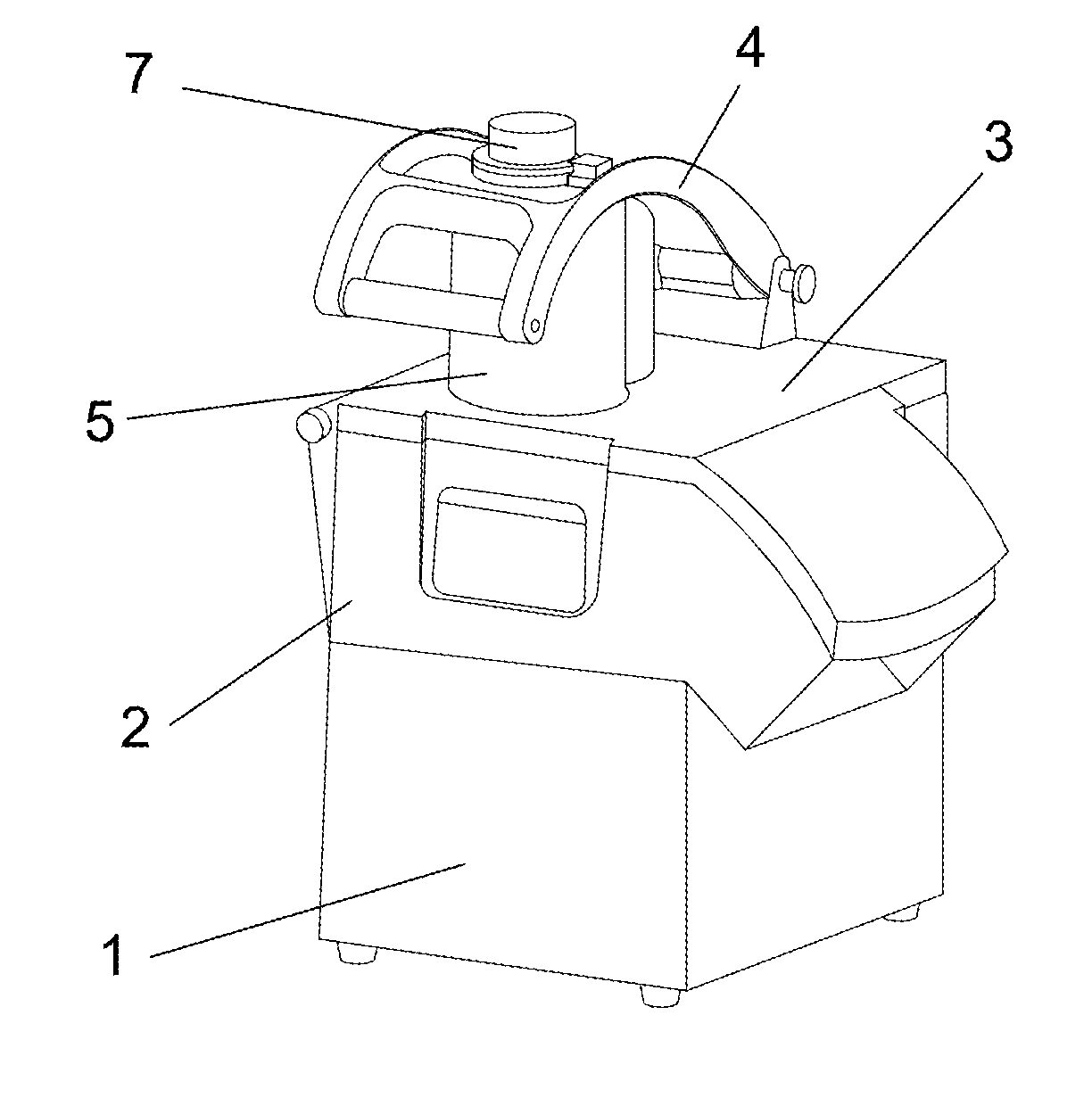
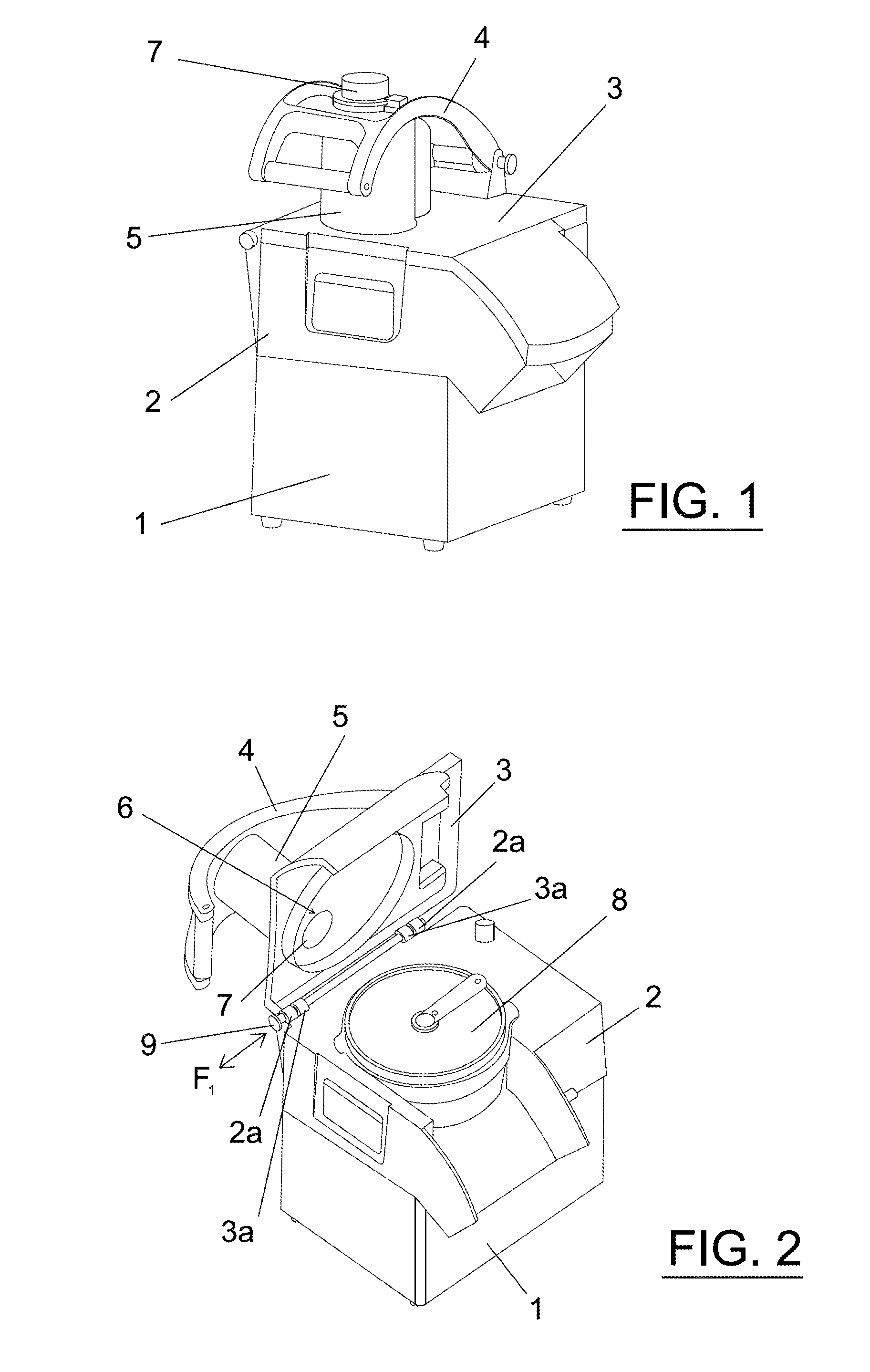
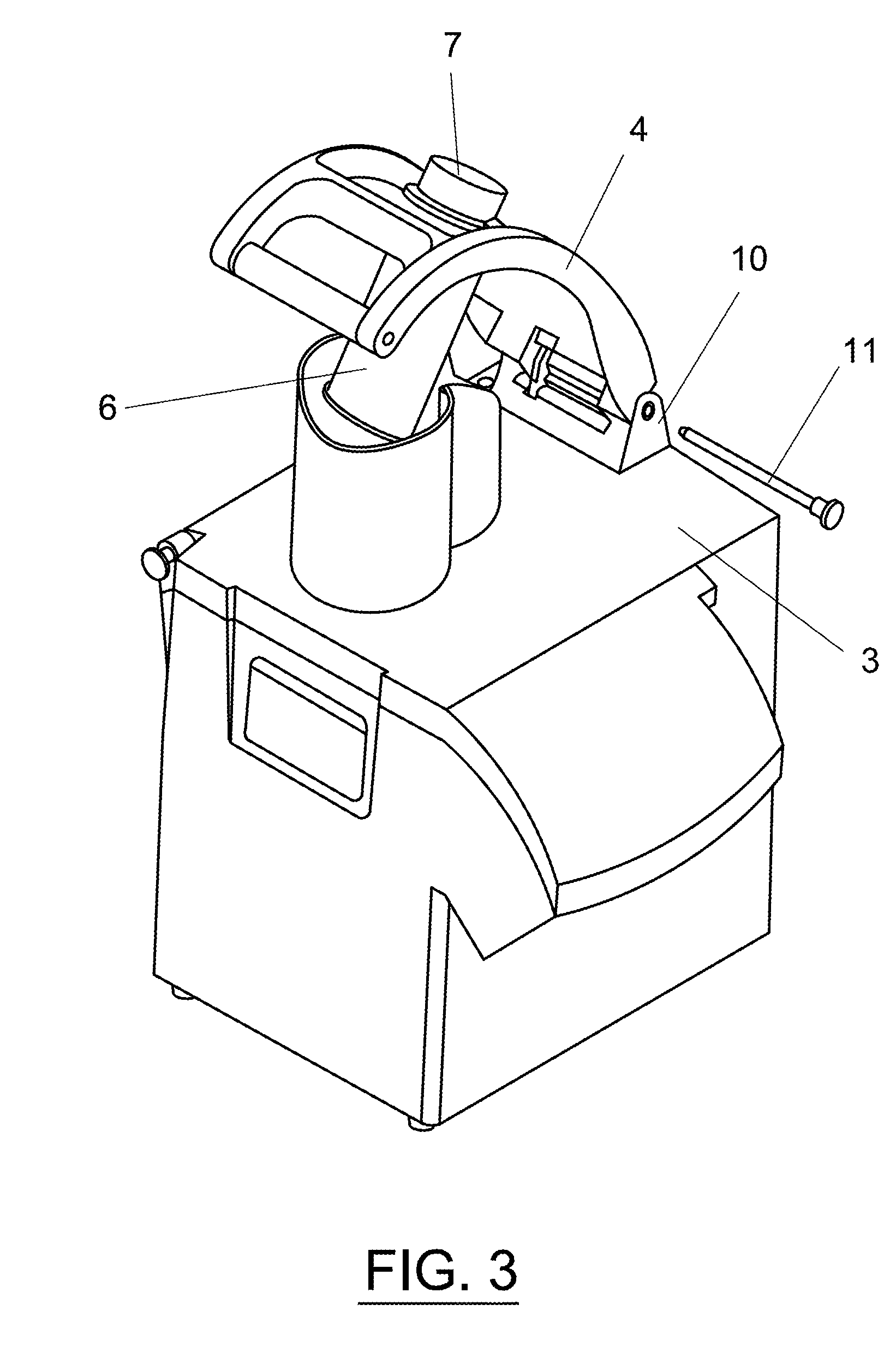
[0028]As mentioned above, the detailed description of the improved vegetable cutting machine proposed by the invention is to be made hereafter with the help of the attached drawings, throughout which the same numerical references are used to designate equal or similar parts. Thus, referring in the first place to the representation of FIG. 1, it is possible to observe a schematic illustration, in perspective, of a vegetable cutting machine built according to the present invention, wherein the set of improvements referred to above has been incorporated, and by means of which it is possible to increase the operating and general maintenance possibilities of the machine. As may be appreciated, the machine responds in general to the traditional design of other machines already in existence, in that it consists of a base 1 that on its top part is closed off by means of a cover 2 on which a part constituting a food feeder 3 is supported and which is associated at its top with a presser 4 co...


PUM


Abstract

A food cutting machine including a base housing a motor, a cover for the base housing a cutting disk, a feeder part joined to the cover, and a feeder mouth which houses a presser to push the food. The presser and food feeder parts are easily removable. Additionally, the presser (4) incorporates a safety lever (15) which activates the power supply switch of the motor (32).

Description

OBJECT OF THE INVENTION[0001]The present invention relates to a vegetable cutting machine, which provides essential novel features and notable advantages in respect of known means used for the same purposes in the current state of the art.[0002]More particularly, the invention proposes the development of a machine designed to cut vegetables, although it is similarly applicable to the treatment and processing of other products such as cheeses, bread, etc., with different finishes such as slices of different thicknesses, dice and sticks, fine strips, thick strips, grated, which provides a device for continuous use in kitchens that offers a set of constructive and functional improvements compared to machines currently known and used for the same purposes, offering greater operational comfort and above all greater functional safety for the user. Additionally, the machine is designed to be dismountable in respect of its functional parts, thereby facilitating integral cleaning thereof.[00...

Claims


Application Information

Patent Timeline
IPC IPC(8): A47J43/00B02C23/02B02C19/00
CPCA47J43/046A47J43/0783B26D7/0641B26D7/00B26D7/0608B26D1/29
Inventor HIDALGO GARCIA, JAVIERAGUIRREZABALAGA ZUBIZARRETA, AITOR
Owner SAMMIC
Why Eureka
Try Eureka