Focal plane shutter and optical apparatus

Inactive Publication Date: 2012-08-23
SEIKO PRECISION INC
View PDF8 Cites 9 Cited by
  • Summary
  • Abstract
  • Description
  • Claims
  • Application Information

AI Technical Summary

Benefits of technology

[0007]It is therefore an object of the present invention to provide a focal plane shutter that suppresses an impact caused by a drive lever. Further, it is another object of the present invention, according to the above object, to provide a focal plane shutter that suppresses the consumption current by suppressing an amount of current in an electromagnet for holding the drive lever.

Problems solved by technology

Therefore, the load applied to the drive lever or the whole focal plane shutter is a factor that reduces the reliability of performance of the focal plane shutter for long-term use.
Therefore, besides the above mentioned impact, there is a problem of an increase in the consumption current resulting from an increase in an amount of current in an electromagnet for holding the drive lever at a given position.

Method used


Image

  • Focal plane shutter and optical apparatus
  • Focal plane shutter and optical apparatus
  • Focal plane shutter and optical apparatus

Examples


Embodiment Construction

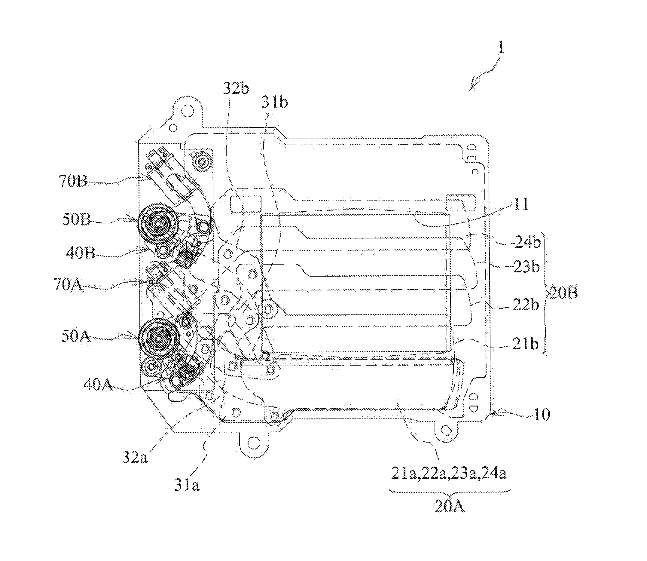
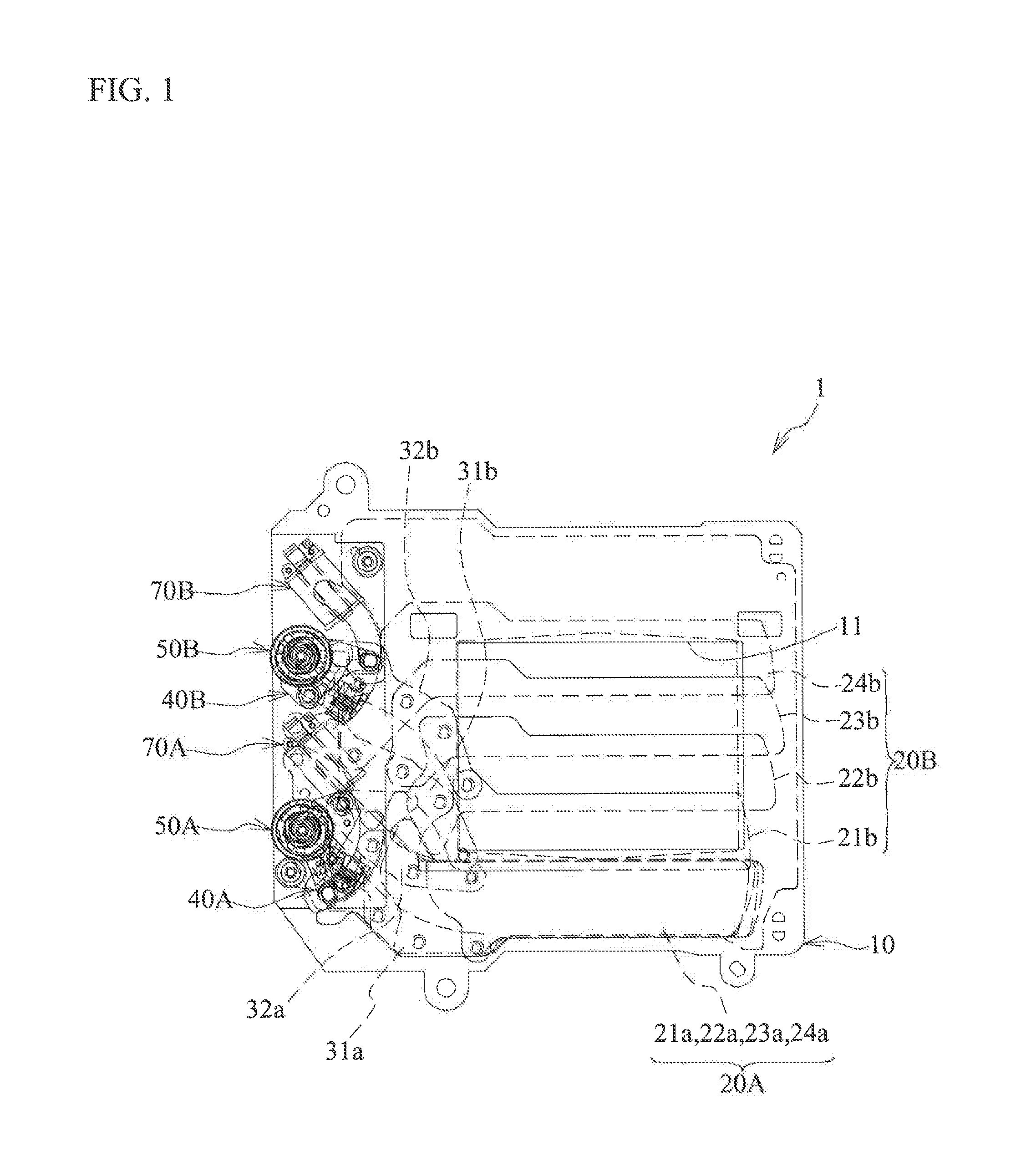
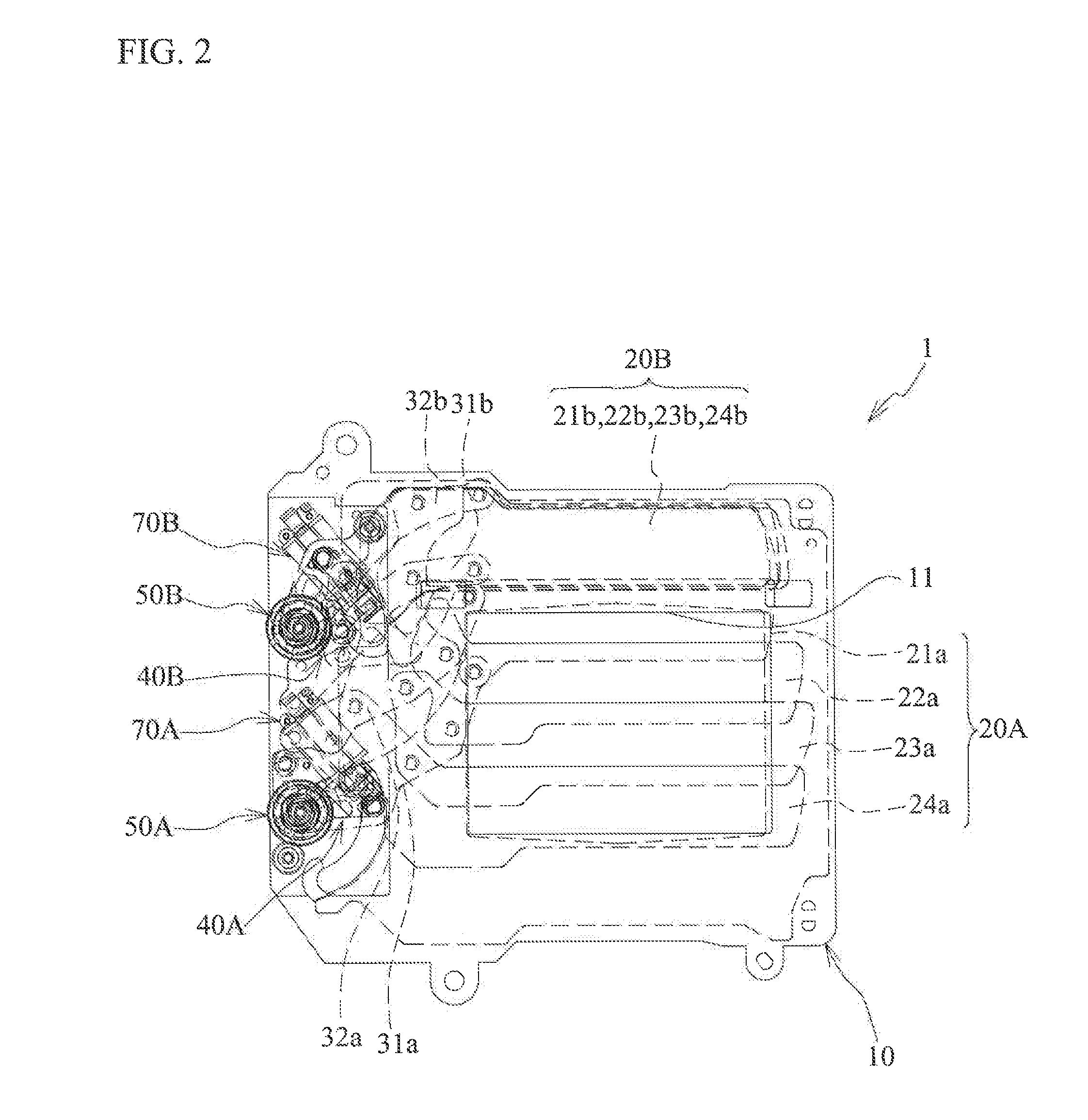
[0020]An embodiment will be described later with reference to the drawings. In the embodiment, a focal plane shutter will be described as an example of a blade driving apparatus. FIG. 1 is a front view of the focal plane shutter. As illustrated in FIG. 1, the focal plane shutter 1 includes: a board 10; blades 21a to 24a and 21b to 24b; drive arms 31a, 32a, 31b, and 32b; an electromagnet 70A for leading blades (hereinafter referred to as electromagnet); and an electromagnet 70B for trailing blades (hereinafter referred to as electromagnet). The board 10 is made of a synthetic resin, and includes an opening 11 with a rectangular shape. Each of the blades 21a to 24a and 21b to 24b is made of a synthetic resin and is thinly formed. Also, each of the drive arms 31a, 32a, 31b, and 32b is made of a metal thin plate. Each of the blades 21a to 24a and 21b to 24b move between a position of receding from the opening 11 and a position of covering at least part of the opening 11.

[0021]Four blade...


PUM


Abstract

A focal plane shutter includes: a board including an opening; a drive lever swingably supported by the board, biased from a start end to a terminal end of a swingable range by a drive spring, and driving blades opening and closing the opening; and a set member rotating in a first direction to position the drive lever at the start end, and then rotating in a second direction.

Description

CROSS-REFERENCE TO RELATED APPLICATION[0001]This application is a continuation of and claims priority to International Patent Application No. PCT / JP2011 / 054079 filed on Feb. 24, 2011, which claims priority to Japanese Patent Application No. 2010-157609 filed on Jul. 12, 2010, subject matter of these patent documents is incorporated by reference herein in its entirety.BACKGROUND[0002](i) Technical Field[0003]The present invention relates to focal plane shutters and optical apparatuses.[0004](ii) Related Art[0005]Japanese Unexamined Patent Application Publication No. 2009-122557 discloses an optical apparatus employing a focal plane shutter. The focal plane shutter is equipped with a board including an opening; blades opening and closing the opening; and a drive lever rotatably supported by the board and driving the blades.[0006]The drive lever is biased by a drive spring, and rotated from a start end to a terminal end of a swingable range by a biasing force of the drive spring. The d...

Claims


Application Information

Patent Timeline
IPC IPC(8): G03B9/40
CPCG03B9/18G03B9/60H04N5/2254G03B9/36G03B19/12G03B13/36H04N23/00
Inventor TAKAHASHI, HIROSHIOISHI, SEIICHI
Owner SEIKO PRECISION INC
Why Eureka
Try Eureka