High-power connector having heat dissipation structure

Inactive Publication Date: 2012-08-23
GUIMA SCI & TECH
View PDF5 Cites 0 Cited by
  • Summary
  • Abstract
  • Description
  • Claims
  • Application Information

AI Technical Summary

Benefits of technology

[0008]In view of the fact that the structural designs of the conventional connectors have yet to be modified in accordance with the design trend of consumer electronics toward greater compactness, and that the resultant heat management problems have compromised the service lives and consumer perception of the affected electronic products, the inventor of the present invention conducted extensive research and experiment and finally succeeded in developing a high-power connector with a heat dissipation structure as disclosed herein. The disclosed structure can rapidly release the heat generated by the high-power connector and thus solve the aforementioned problems effectively.
[0009]It is an object of the present invention to provide a high-power connector having a heat dissipation structure, wherein the connector takes substantially the same form as the conventional connectors but is additionally provided with a plurality of auxiliary metal plates for reducing the impedance of the high-power connector and thereby significantly extending the connector's service life. The high-power connector includes a cover, a plurality of resilient metal terminals, and a plurality of auxiliary metal plates. The cover is made of an insulating material and defines a plurality of receiving spaces therein. The resilient metal terminals are fitted in the receiving spaces respectively. The front section of each resilient metal terminal has an arcuate shape, passes through a lateral side of the cover, and is exposed from the cover. The front section of each auxiliary metal plate is electrically connected to the corresponding resilient metal terminal, and the rear section of each auxiliary metal plate is electrically connected to a circuit board. As the auxiliary metal plates have relatively low impedance, the components of the high-power connector are prevented from premature aging attributable to high temperature.
[0010]It is another object of the present invention to provide the foregoing high-power connector, wherein the rear section of each resilient metal terminal is electrically connected to the circuit board. Thus, each resilient metal terminal and the corresponding auxiliary metal plate form a parallel circuit to reduce the overall impedance of the high-power connector. Moreover, the impedance of each auxiliary metal plate can be lower than that of the corresponding resilient metal terminal. With the auxiliary metal plates having the lower impedance, the electric current in each resilient metal terminal will choose to flow through the corresponding auxiliary metal plate, before reaching the circuit board. Thus, the heat generated by the high-power connector can be effectively reduced.
[0011]Still another object of the present invention is to provide the foregoing high-power connector, wherein the connector is inserted through and embedded in the circuit board so as to minimize the space occupied by both the high-power connector and the circuit board. This gives designers more flexibility in planning the circuit space of an electronic device using the high-power connector.

Problems solved by technology

Further, as a consumer electronic product is downsized, so must be its electronic components; otherwise, the desired variety of electronic components (e.g., connectors, resistors, capacitors, etc.) cannot be fitted into the product's limited interior space.
However, the downsizing of the electronic components not only increases the design complexity of the consumer electronic product, but also gives rise to heat management issues that need to be addressed during the design phase, for the impedance of a metal terminal increases as the thickness, and hence the cross-sectional area, of the terminal is reduced.
Nonetheless, a larger battery capacity means a larger supply current from the battery and consequently a larger amount of heat generated by the connector electrically connected to the battery.
As previously mentioned, given the trend toward miniaturization of consumer electronics, existing connectors are only downsized proportionally but are not modified in structural design; hence, these connectors suffer from low heat dissipation efficiency.
As a result, the heat accumulated in the connector 1 cannot be efficiently dissipated, and the temperature of the entire connector 1 rises rapidly, thus not only subjecting the components of the connector 1 to the risks of premature aging caused by extended exposure to high heat, but also shortening the service lives of the electronic components adjacent to the connector 1.
This vicious circle will cut short the service life of the consumer electronic product equipped with the connector 1 and impair the quality of all products using such a connector.
Consequently, the manufacturers will have to face customer complaints or even loss of customers.
To sum up, the structures of the conventional connectors have not been changed according to the current design trend of consumer electronics toward smaller and lighter products, so heat accumulation is very likely to occur in the conventional connectors and cause serious heat management problems to those consumer electronic products using such connectors.
Therefore, it is an important issue in the electronic industry to design a novel connector which satisfies the size requirements of increasingly smaller consumer electronics, which has better performance than its prior art counterparts, and whose electronic components, though densely packed in a limited space, still allow good heat dissipation.

Method used


Image

  • High-power connector having heat dissipation structure
  • High-power connector having heat dissipation structure
  • High-power connector having heat dissipation structure

Examples


first embodiment

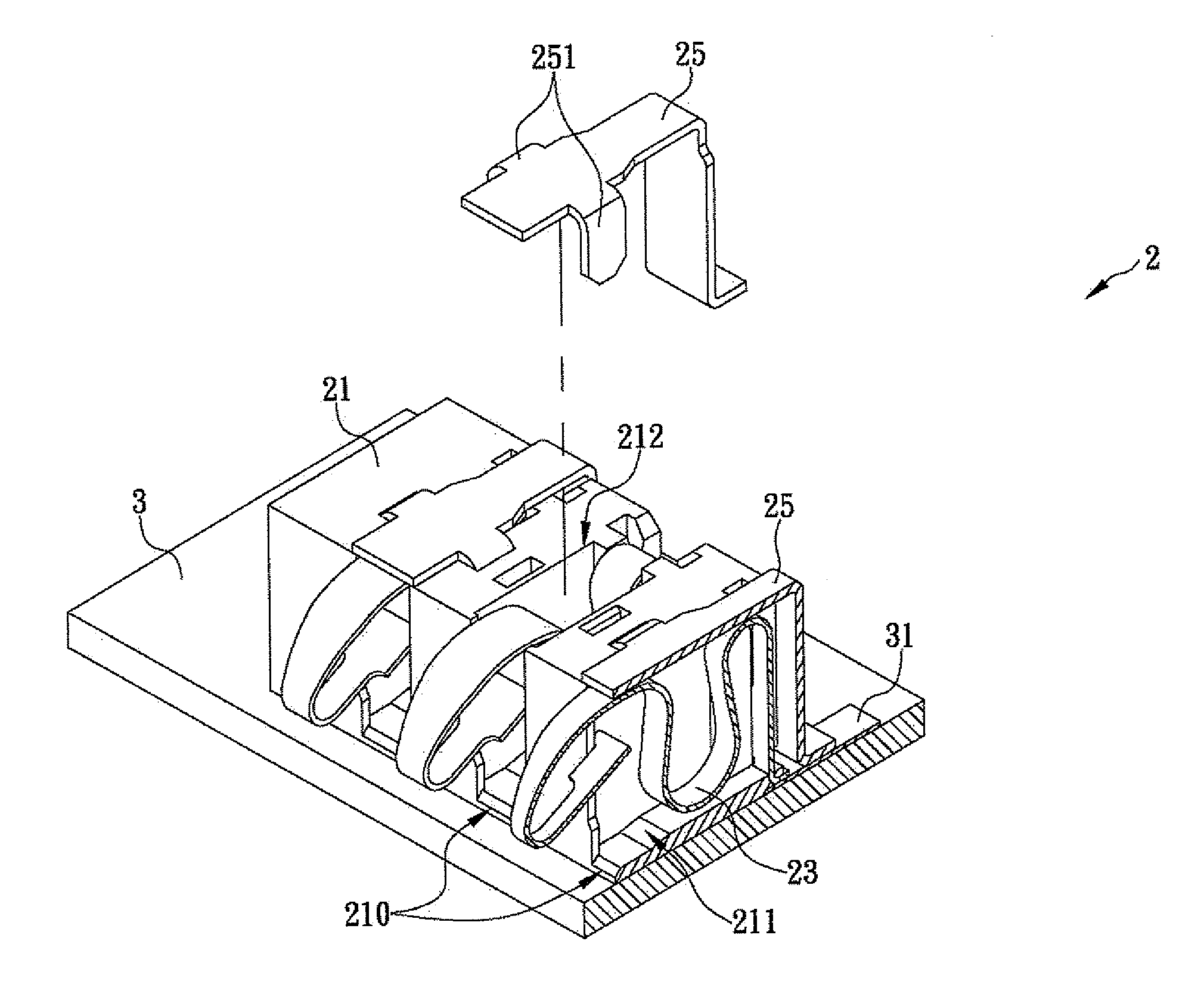
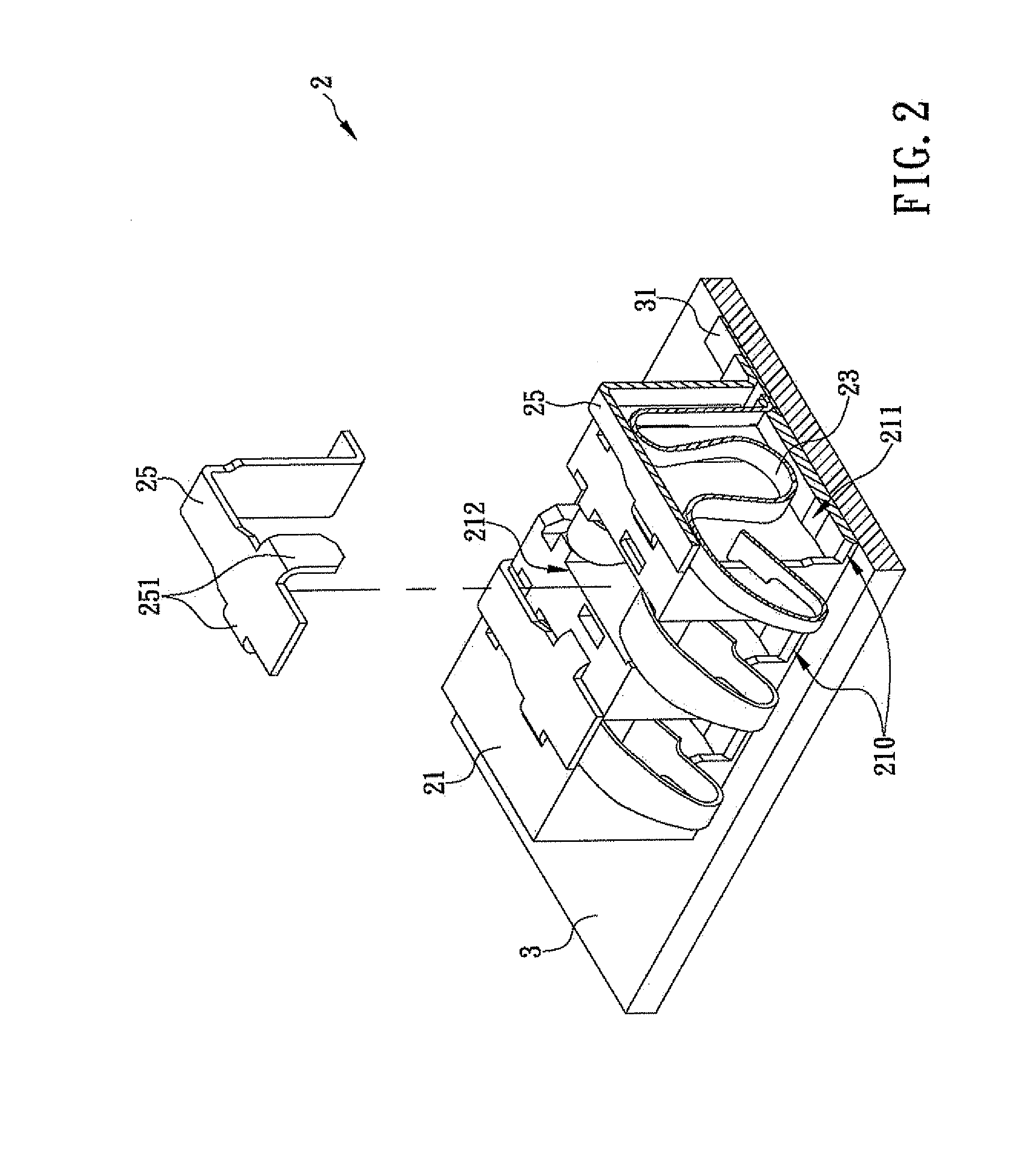
[0021]Referring again to FIG. 2, in order to prevent the auxiliary metal plates 25 being pressed from shifting away from their original positions and hindering normal operation of the high-power connector 2, the front section of each auxiliary metal plate 25 is provided with a positioning portion 251. The positioning portions 251 are engaged with the cover 21 to secure the resilient metal plates 25 firmly in position. Thus, the high-power connector 2 in the first embodiment achieves the following advantageous effects:

[0022](1) As the front section and the rear section of each resilient metal terminal 23 are respectively and electrically connected to the front section and the rear section of the corresponding auxiliary metal plate 25, each pair of the connected resilient metal terminal 23 and auxiliary metal plate 25 form a parallel circuit. Given the equation of parallel-connected resistors: total impedance R=(R1*R2) / (R1+R2), where R1 represents the impedance of the resilient metal ...

fourth embodiment

[0028]Reference is now made to FIG. 5. The electrode terminals 61 of a conventional battery 6 may have different shapes in order to meet different circuit requirements. For instance, the electrode terminal 61A has a relatively wide area of contact, and the plural electrode terminals 61 belong to the same line and can therefore be viewed as a single electrode terminal 61. In the present invention as shown in FIG. 5, a connecting plate 751 is provided between the two adjacent auxiliary metal plates 75 to add to the widths of the auxiliary metal plates 75, and the auxiliary metal plate 75A itself has a relatively great width to significantly increase the heat dissipation area of the high-power connector 7. Therefore, the high-power connector 7 of the present invention has wide industrial applicability and can satisfy different circuit design requirements, giving the connector designers or manufacturers a competitive edge in the market.


PUM


Abstract

The present invention is to provide a high-power connector having a heat dissipation structure, which includes a cover, a plurality of resilient metal terminals and a plurality of auxiliary metal plates. The cover is made of an insulating material and defines a plurality of receiving spaces therein. The resilient metal terminals are fitted in the receiving spaces respectively. The front section of each resilient metal terminal has an arcuate shape, passes through a lateral side of the cover, and is exposed from the cover. The front section of each auxiliary metal plate is electrically connected to the corresponding resilient metal terminal, and the rear section of each auxiliary metal plate is electrically connected to a circuit board. Since the auxiliary metal plates have relatively low impedance capable of rapidly releasing the heat generated by the connector, the components of the connector are prevented from premature aging attributable to high temperature.

Description

FIELD OF THE INVENTION[0001]The present invention relates to an electrical connector, more particularly to a high-power connector having a heat dissipation structure, which includes a plurality of auxiliary metal plates each having relatively low impedance for rapidly releasing the heat generated by the high-power connector to the outside and thus preventing the components of the high-power connector from premature aging attributable to high temperature.BACKGROUND OF THE INVENTION[0002]With the improvement of people's living standard, one who wishes to buy a certain electronic product would pay as much attention to the physical appearance of the electronic product as to the product's functions, and this is especially true of consumer electronics such as mobile phones, personal digital assistants (PDAs), and tablet PCs. Nowadays, with a view to high portability and easy storage, it is generally desired that the physical appearance of a consumer electronic product conform to the desig...

Claims


Application Information

Patent Timeline
IPC IPC(8): H01R13/00
CPCH01R13/2428H01R12/724
Inventor CHIU, HSIEN-YULIN, SHIN-WAYCHU, HAN-MIN
Owner GUIMA SCI & TECH
Why Eureka
Try Eureka