Water stop treatment method and insulating covered electric wire

a technology of insulating covered electric wire and water stop treatment, which is applied in the direction of insulating conductors, cables, conductors, etc., can solve problems such as giving damage, and achieve the effect of simple and assured prevention, simple and light structur

Active Publication Date: 2012-08-30
YAZAKI CORP
View PDF4 Cites 8 Cited by
  • Summary
  • Abstract
  • Description
  • Claims
  • Application Information

AI Technical Summary

Benefits of technology

[0032]According to the water stop treatment method and the insulating covered electric wire of the present invention, water can be avoided from entering the ground terminal side of the insulating covered electric wire from a drain wire drawn out from a terminal of a shied wire. Accordingly, the water can be simply and assuredly prevented from moving (entering) to a circuit or electronic parts of a circuit board through the insulating covered electric wire. Consequently, the insulation deterioration or the short-circuit accident of the circuit or the electronic parts can be assuredly avoided by a simple and light structure.
[0033]Further, since the water stopping agent dropped to the exposing part from which a part of the c

Problems solved by technology

However, when the shield wire is arranged in a watering area, for instance, when the engine room is to be cleaned, there is a fear that water droplets putting on the drain wire due to the wa

Method used


Image

  • Water stop treatment method and insulating covered electric wire
  • Water stop treatment method and insulating covered electric wire
  • Water stop treatment method and insulating covered electric wire

Examples


Embodiment Construction

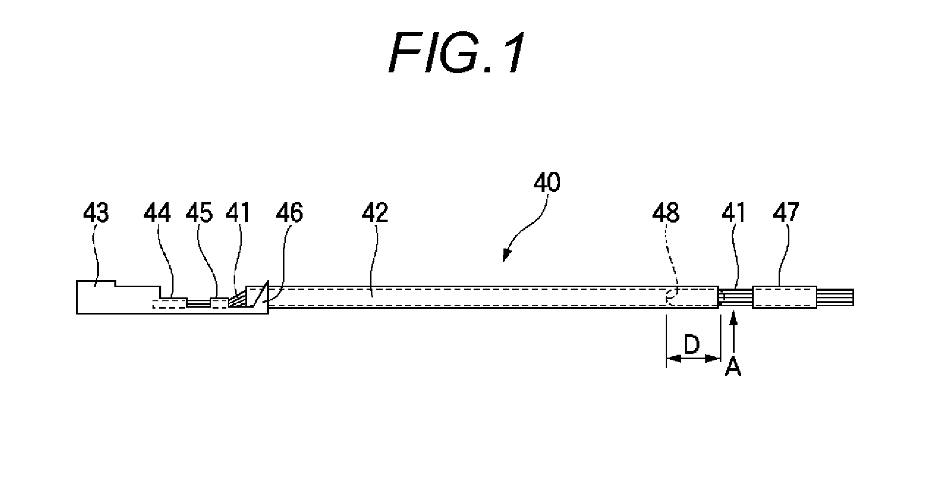
[0059]Now, a preferable exemplary embodiment of an insulating covered electric wire and a water stop treatment method therefore according to a mode for carrying out the invention will be described below by referring to the drawings. The insulating covered electric wire having a ground terminal in one end will be described as an example.

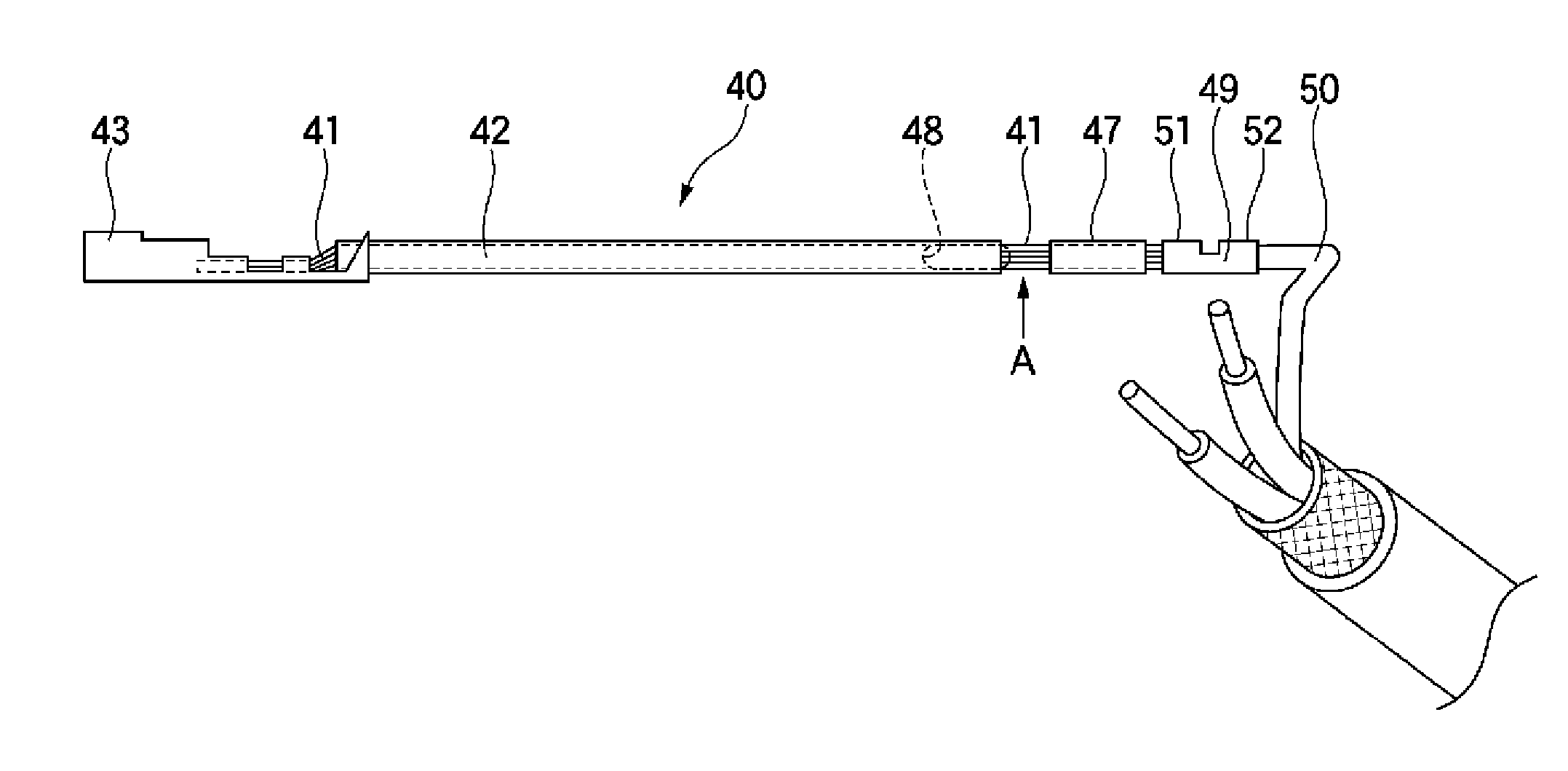
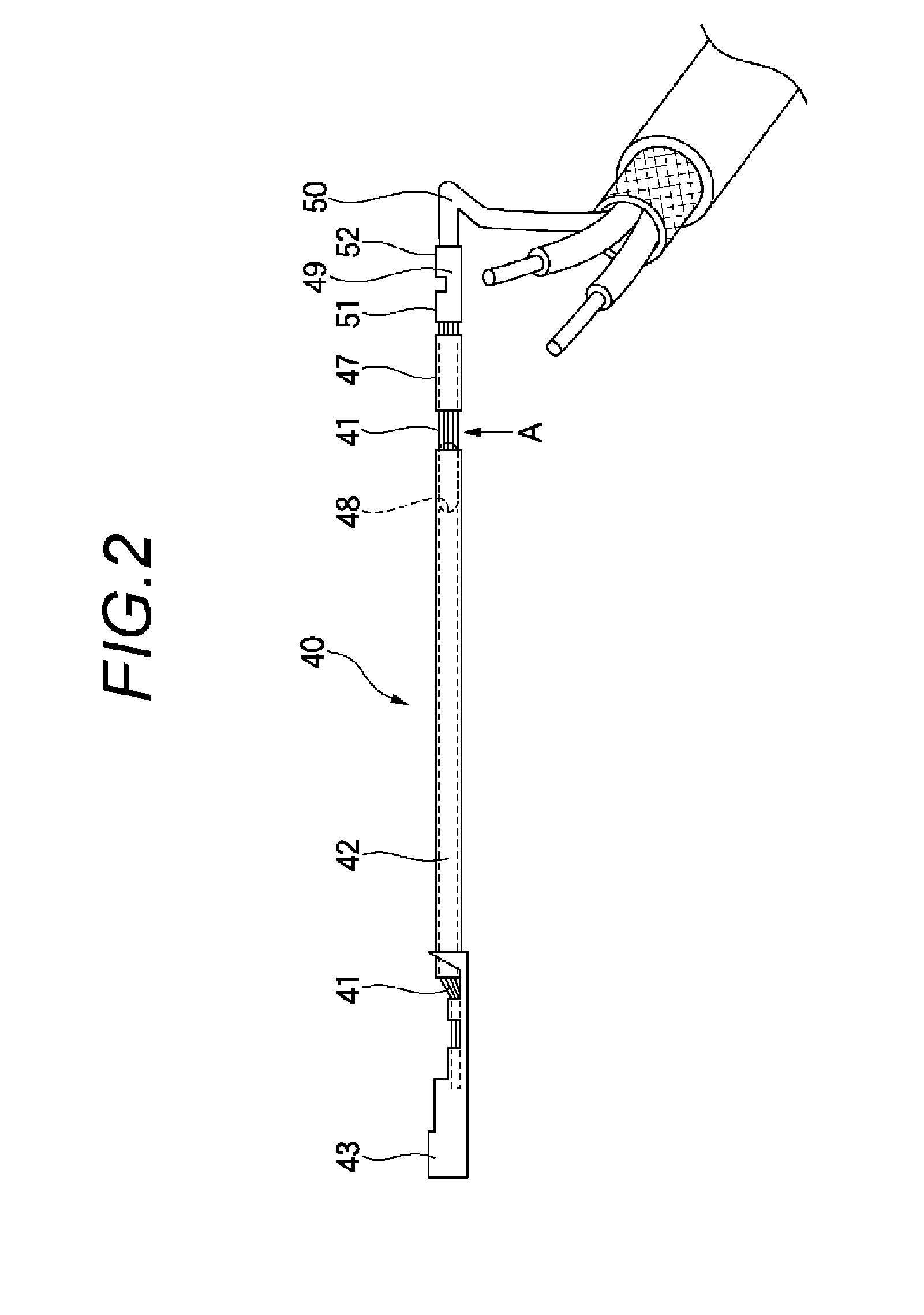
[0060]Here, FIG. 1 is a front view conceptually showing an exemplary embodiment of an insulating covered electric wire according to the embodiment. FIG. 2 is a front view showing a state in which the insulating covered electric wire shown in FIG. 1 is connected to a drain wire. FIG. 3 is a front view showing a state in which the insulating covered electric wire and the drain wire shown in FIG. 2 are covered with a binding tape. FIG. 4A to FIG. 4I are explanatory diagrams showing procedures for applying a water stop treatment to the insulating covered electric wire shown in FIG. 1. FIG. 5A to FIG. 5I are explanatory diagrams showing another procedures ...


PUM


Abstract

A water stopping treatment simply and assuredly prevents water from moving or entering to a circuit board or the like. A one end of a core wire (41) is exposed from an insulation cover (42). An exposing part (A) that is peeled off from the insulation cover (42) and exposed from the insulation cover (42) is formed at an arbitrary position from the one end to the other end of the core wire. A water stopping agent (48) is filling from the exposing part (A) toward the other end of the core wire (41).

Description

TECHNICAL FIELD [0001]The present invention relates to an insulating covered electric wire connected to a drain wire drawn out from a terminal of a shield electric wire and a water stop treatment method of the insulating covered electric wire.BACKGROUND ART [0002]For a wire harness arranged in an engine room of a vehicle, a shield wire is used which has a drain wire provided together with an insulating covered electric wire. By installing the drain wire, noise can be more effectively prevented from being mixed in a signal supplied to a core wire of the insulating covered electric wire. Since the drain wire needs to be electrically connected to a braided wire for a shield, the drain wire itself is not coated with insulation.[0003]However, when the shield wire is arranged in a watering area, for instance, when the engine room is to be cleaned, there is a fear that water droplets putting on the drain wire due to the watering area may move along the drain wire to be put on a circuit or ...

Claims


Application Information

Patent Timeline
IPC IPC(8): H01B7/28H01R43/00
CPCH01R4/18H01R4/70Y10T29/49195H01B7/285B60R16/0215H01B7/28
Inventor KURIYAGAWA, MASARU
Owner YAZAKI CORP
Why Eureka
Try Eureka