Closed loop control of auxiliary injection unit

Active Publication Date: 2012-08-30
MOLD MASTERS 2007
View PDF9 Cites 25 Cited by
  • Summary
  • Abstract
  • Description
  • Claims
  • Application Information

AI Technical Summary

Problems solved by technology

The drawback of open loop control is that it provides no mechanism by which the actual molding conditions presented by the flow of the first melt stream injected by the primary injection unit may influence the commencement, speed and/or pressure of the flow of the seco

Method used


Image

  • Closed loop control of auxiliary injection unit
  • Closed loop control of auxiliary injection unit
  • Closed loop control of auxiliary injection unit

Examples


Embodiment Construction

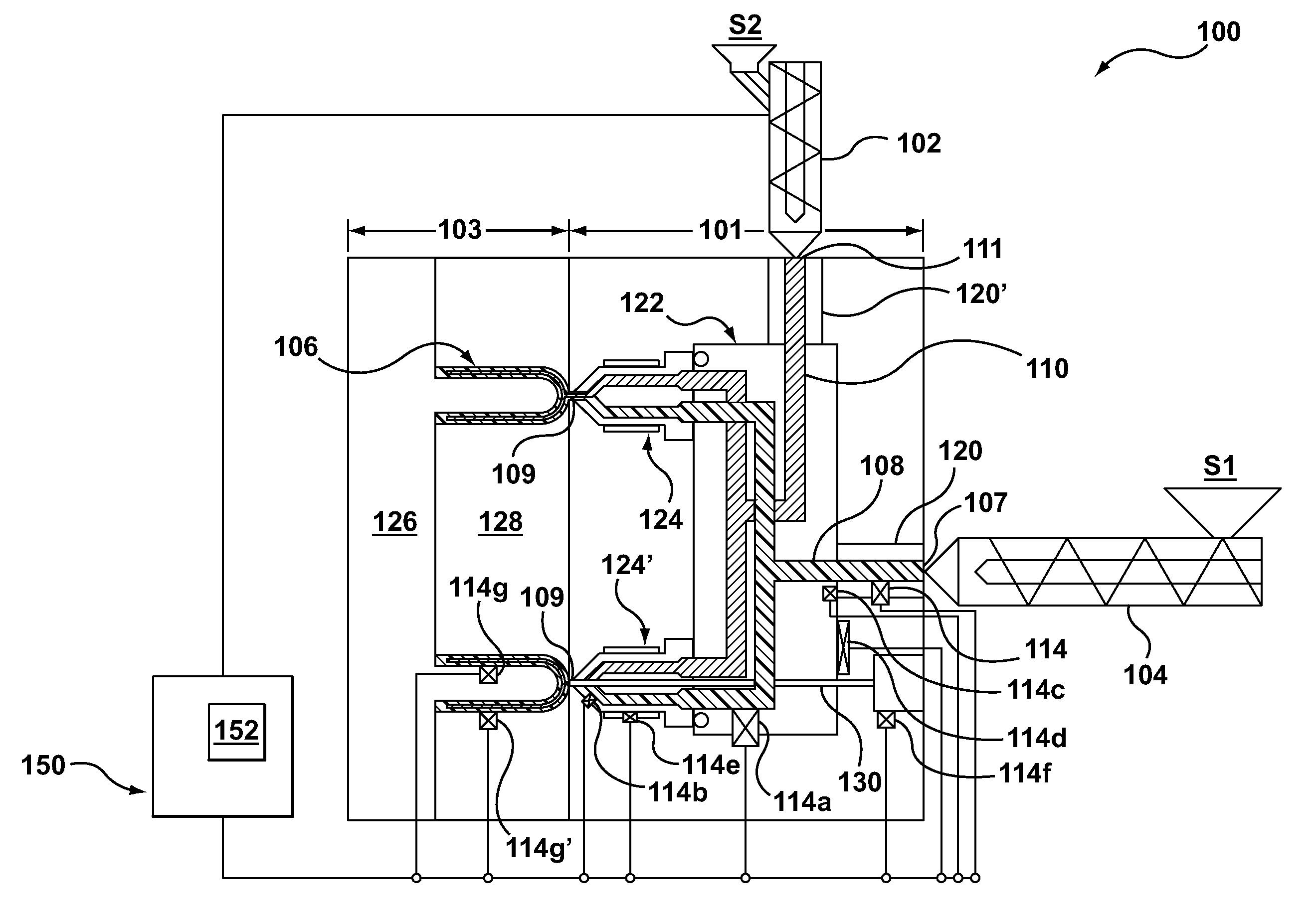
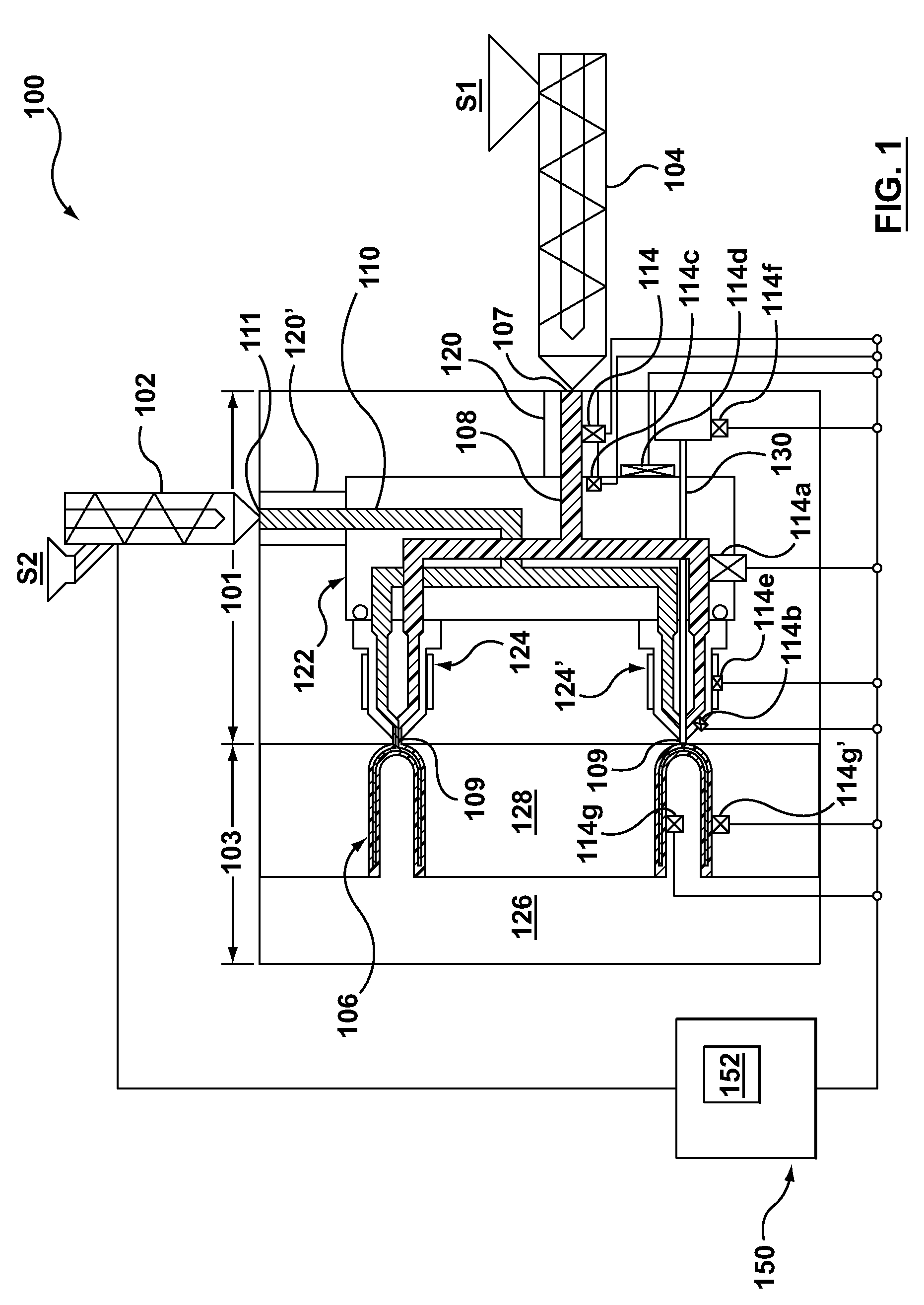
[0016]Specific embodiments are now described with reference to the figures. The following detailed description is merely exemplary in nature and is not intended to limit the invention or the application and uses of the invention. In the following description, “downstream” is used with reference to the direction of mold material flow from an injection unit to a mold cavity of an injection molding system, and also to the order of components or features thereof through which the mold material flows from an injection unit to a mold cavity, whereas “upstream” is used with reference to the opposite direction. Although the description of embodiments hereof is in the context of co-injection and multi-material applications of a hot runner injection molding systems, the invention may also be used in other molding arrangements where it is deemed useful. Furthermore, there is no intention to be bound by any expressed or implied theory presented in the preceding technical field, background, brie...


PUM

PropertyMeasurementUnit
Timeaaaaaaaaaa
Pressureaaaaaaaaaa
Moldableaaaaaaaaaa

Abstract

A method and apparatus of controlling commencement of an injection of a melt stream of moldable material from an auxiliary injection unit. A sensor is placed in an injection molding system to sense a condition related to an injection of a first melt stream of a first moldable material provided by a primary injection unit. Commencement of a second melt stream of a second moldable material from the auxiliary injection unit is initiated upon the sensed condition related to the injection of the first melt stream being detected at a preselected value. The sensed condition may be a pressure, velocity or temperature of the first melt stream as provided by a direct sensor, a force or strain on a hot runner component as provided by an indirect sensor or the occurrence of a function of the injection molding system as provided by a functional sensor.

Description

FIELD OF THE INVENTION[0001]The invention relates generally to injection molding systems that have an auxiliary injection unit for co-injection or multi-material applications. More particularly, the invention relates to closed loop control of the auxiliary injection unit.BACKGROUND OF THE INVENTION[0002]It is known in the art of injection molding to simultaneously or sequentially inject two melt streams of moldable material into a mold cavity using a single hot runner injection molding nozzle, which is commonly referred to as co-injection. A first melt steam of a first moldable material may be provided by an injection molding machine, which may be referred to as a primary injection unit, while a second melt stream of a second moldable material may be provided by an auxiliary injection unit. The first and second melt streams are fed from their respective injection units into respective, separate first and second melt channels or runners of a manifold that are likewise in fluid commun...

Claims


Application Information

Patent Timeline
IPC IPC(8): B29C45/76
CPCB29C45/1615B29C45/164B29C45/76B29C2045/2722B29C2045/279B29C2945/76006B29C2945/76013B29C2945/76103B29C2945/7611B29C2945/76274B29C2945/76381B29C2945/76481B29C2945/76555B29C2945/76752B29C2945/76779B29C2945/76859B29K2105/253B29C2945/7604B29C2945/76056B29C2945/76454B29C2945/76648B29C2945/76936B29C45/762B29C45/77B29C45/78B29C45/16
Inventor CATOEN, BRUCEGAMMON, SCOTT
Owner MOLD MASTERS 2007
Why Eureka
Try Eureka