
Disruptor Guidance System and Methods Based on Scatter Imaging

Active Publication Date: 2012-08-30
AMERICAN SCI & ENG INC
View PDF5 Cites 2 Cited by
  • Summary
  • Abstract
  • Description
  • Claims
  • Application Information

AI Technical Summary

Problems solved by technology

Difficulties arise in this process due to the fact that the internal components of such a device may not be visible without physical manipulation of the device or without moving or removing various components of the device.
Accordingly, resolving the type and amount of explosives involved and confirming how the device is wired and where the trigger mechanism or mechanisms are located at a level of accuracy that allows a technician to safely disarm the explosive devices with a tactical robot often proves challenging.

Method used


Image

  • Disruptor Guidance System and Methods Based on Scatter Imaging
  • Disruptor Guidance System and Methods Based on Scatter Imaging
  • Disruptor Guidance System and Methods Based on Scatter Imaging

Examples


Embodiment Construction

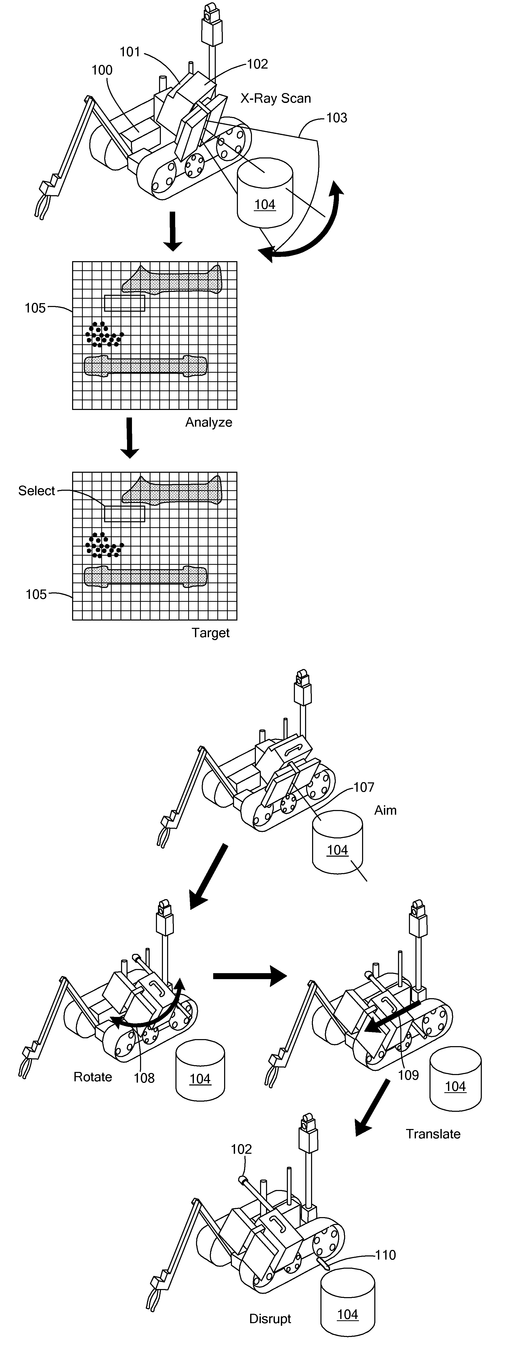
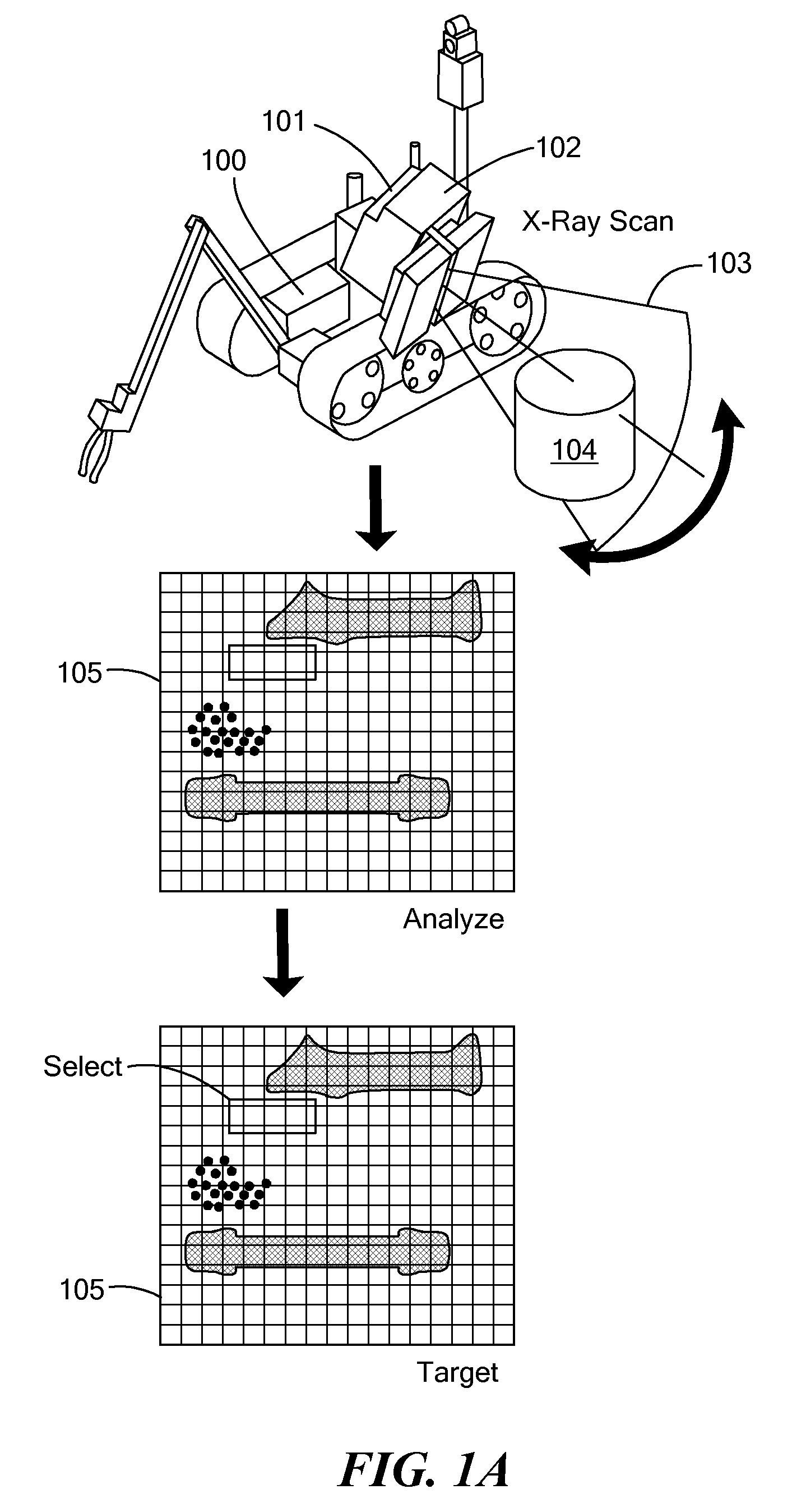
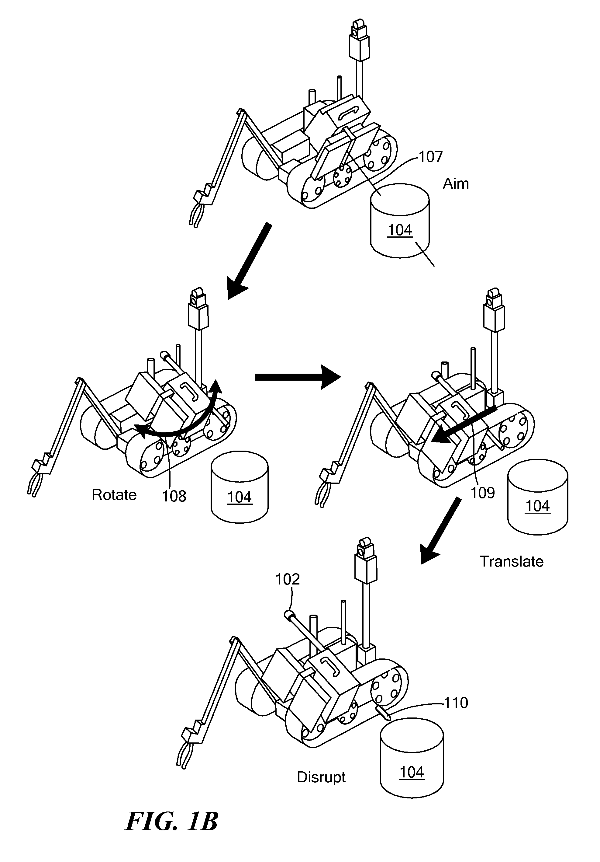
[0005]A first embodiment of the invention provides a system for guiding a disruptor robot in disruption of an explosive device. The system includes a source of penetrating radiation, having a coordinated position on the robot with respect to a disruptor coupled to the robot, at least one detector for detecting radiation produced by the source and scattered by the explosive device, an analyzer for producing an image of the explosive device including a disruption target of the explosive device, and a controller for positioning the disruptor with respect to the explosive device so that the disruptor is aimed at the disruption target. Positioning the disruptor may include positioning the robot. The radiation may be x-ray radiation, and the radiation scattered by the explosive device may include backscattered radiation. The image may be a 3-dimensional image.

[0006]In a related embodiment, the source may include a collimator adapted to collimate the penetrating radiation into a pencil bea...


PUM


Abstract

A system and method for guiding a disruptor robot in disruption of an explosive device. The system includes a source of penetrating radiation, having a coordinated position on the robot with respect to a disrupter coupled to robot, and at least one detector for detecting radiation produced by the source and scattered by the explosive device. An analyzer produces an image of the explosive device and facilitates identification of a disruption target of the explosive device. A controller positions the disruptor with respect to the explosive device so that the disruptor is aimed at the disruption target.

Description

[0001]This application claims priority from U.S. provisional patent application Ser. No. 61 / 304,046, filed Feb. 12, 2010, and entitled, “Disruptor Guidance System and Methods Based on Scatter Imaging.” This application also claims priority from U.S. provisional patent application Ser. No. 61 / 314,336, filed Mar. 16, 2010, and also entitled “Disruptor Guidance System and Methods Based on Scatter Imaging.” Each of these applications is hereby incorporated by reference herein in its entirety.TECHNICAL FIELD[0002]The present invention relates to operating an explosive device disruptor, and, more particularly, to using a penetrating radiation imaging system to direct operation of the disruptor.BACKGROUND ART[0003]Disarming an explosive device such as an improvised explosive device (IED) requires careful analysis of the device and an identification of various components of the device such as a power source, trigger mechanisms, explosive materials, and wiring connections. An explosive ordna...

Claims


Application Information

Patent Timeline
IPC IPC(8): G05B15/00
CPCF41B9/0046F41H11/16F41H11/32F41H7/005F41H11/28F42D5/04
Inventor MCELROY, TERRYPASCOE, JIM
Owner AMERICAN SCI & ENG INC
Learn More