Mechanical Liner Drilling Cementing System

a cementing system and mechanical liner technology, applied in the direction of drilling machines and methods, fluid removal, borehole/well accessories, etc., to achieve the effect of reducing the number of trips, reliable, and cost-effective cementing of the liners

Inactive Publication Date: 2012-09-06
SCHLUMBERGER TECH CORP
View PDF16 Cites 35 Cited by
  • Summary
  • Abstract
  • Description
  • Claims
  • Application Information

AI Technical Summary

Benefits of technology

[0013]In accordance with another embodiment of the present invention, a system for cementing a liner string suspended from an end of a wellbore casing string by a liner hanger, and setting a liner top packer in the casing string above the liner hanger comprises a running tool, a packer setting tool, a liner top packer, a double flapper valve, and a tie back nipple. The running tool defines a central bore for passage of cement and drilling mud, the central bore having an axis. The packer setting tool couples to the running tool so that rotation of the running tool will actuate the packer setting tool to set the liner top packer with the running tool and upwards axial pull will actuate the packer setting tool to release the packer setting tool from the liner top packer. The liner top packer releasably mounts to the packer setting tool at an upper end of the liner top packer. The double flapper valve couples to a lower end of the liner top packer so that after removal of the packer setting tool from the well bore the double flapper will prevent fluid flow in two directions through the valve. The tie back nipple couples to a lower end of the double flapper valve and is configured to engage a liner top.
[0015]An advantage of embodiments disclosed herein is that the present system allows use of existing liner cement plugs and provides a back up flow barrier to a latch down plug. This is needed in the event the pumps are stopped before the plug reaches its landing receptacle or in the event the plug fails. It provides a reliable, cost effective means to effectively cement drilled in liners while reducing the number of trips required to cement the liner. The present system also eliminates the need for a wiper plug to latch and hold back cement, reducing the risk of cement backflow while setting the packer.

Problems solved by technology

This fractures the shear screw and urges the adapter sleeve against the packer assembly to set the packer assembly.

Method used


Image

  • Mechanical Liner Drilling Cementing System
  • Mechanical Liner Drilling Cementing System
  • Mechanical Liner Drilling Cementing System

Examples


Embodiment Construction

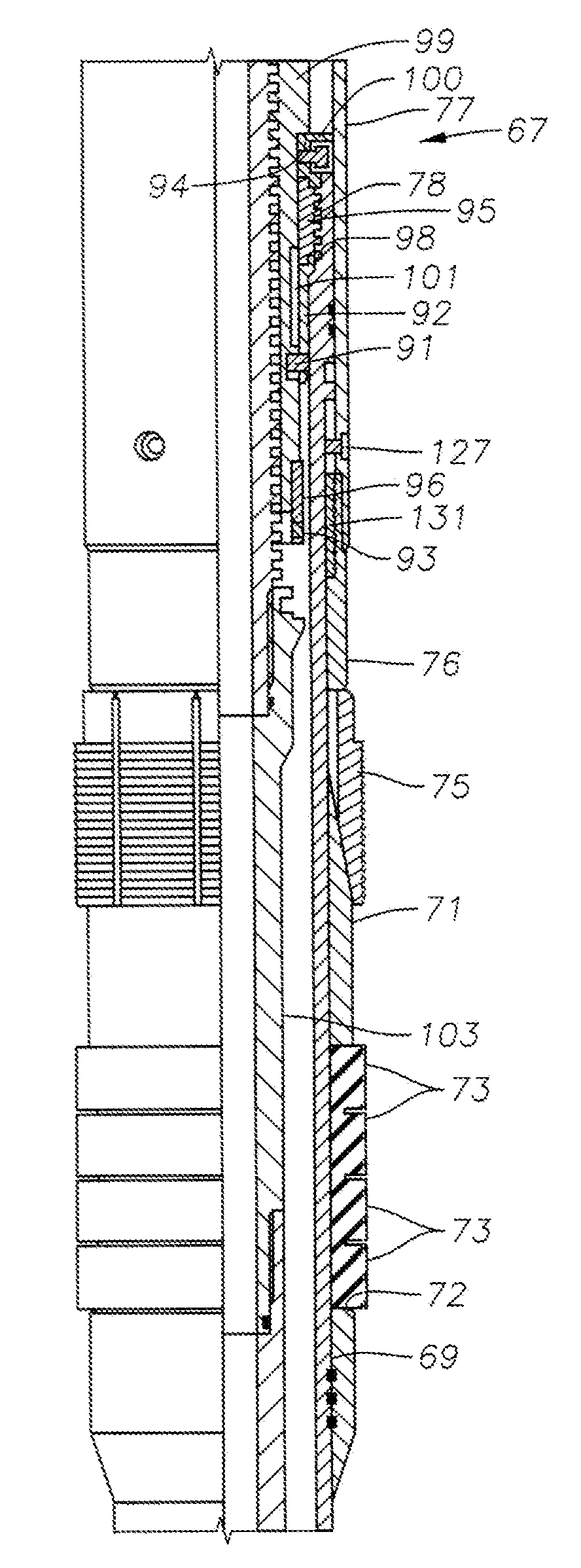
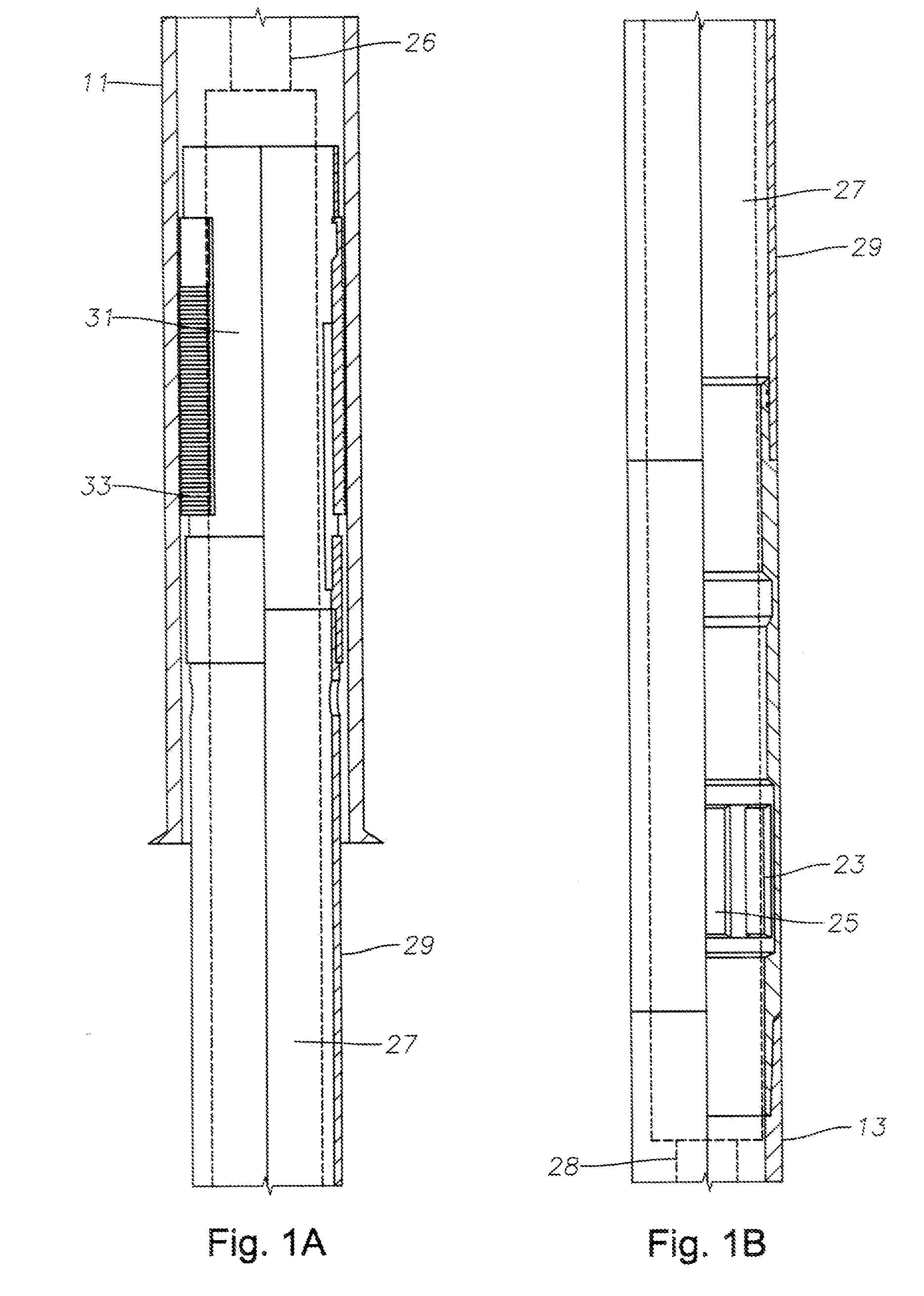
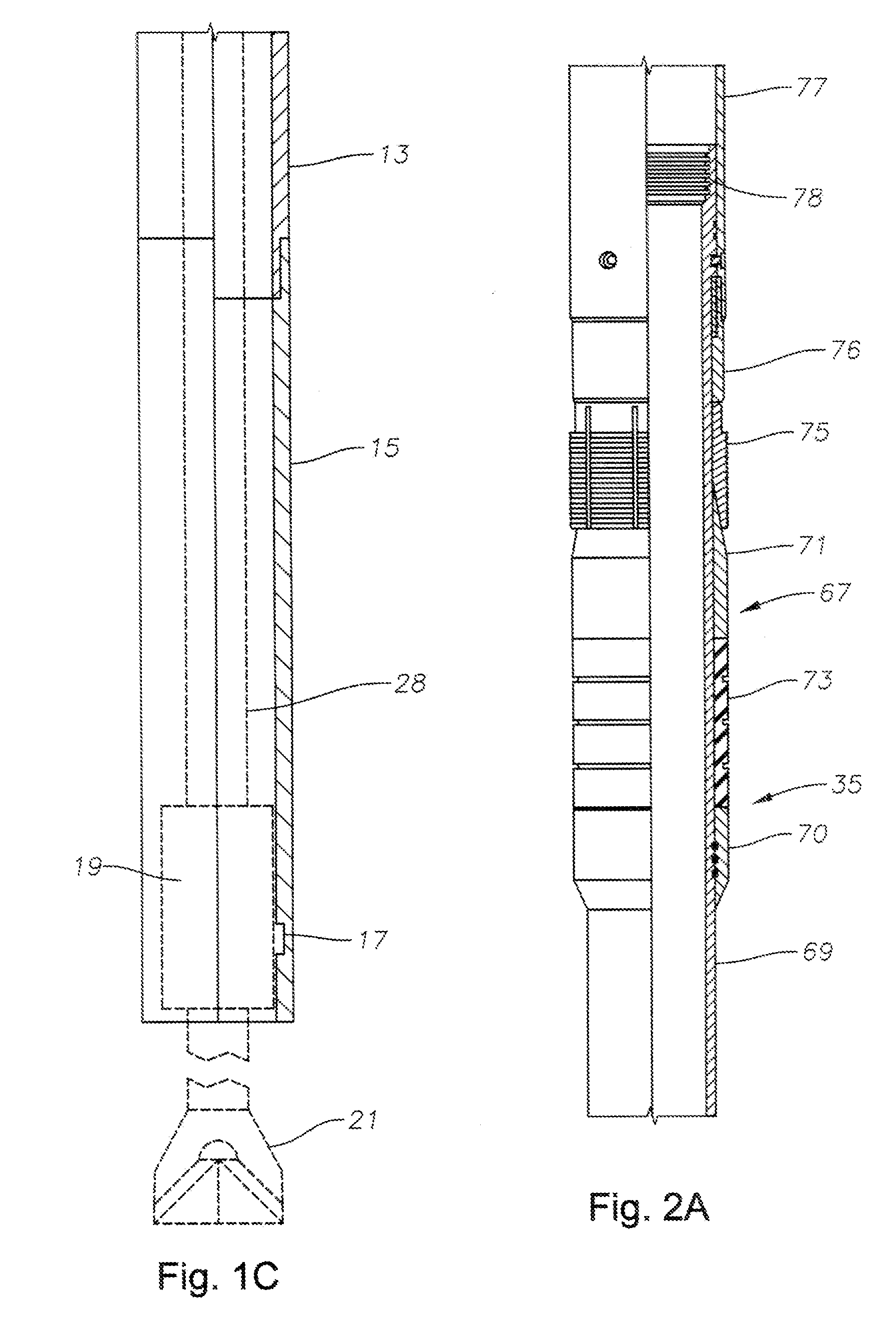
[0030]The present invention will now be described more fully hereinafter with reference to the accompanying drawings which illustrate embodiments of the invention. This invention may, however, be embodied in many different forms and should not be construed as limited to the illustrated embodiments set forth herein. Rather, these embodiments are provided so that this disclosure will be thorough and complete, and will fully convey the scope of the invention to those skilled in the art. Like numbers refer to like elements throughout, and the prime notation, if used, indicates similar elements in alternative embodiments.

[0031]In the following discussion, numerous specific details are set forth to provide a thorough understanding of the present invention. However, it will be obvious to those skilled in the art that the present invention may be practiced without such specific details. Additionally, for the most part, details concerning drilling rig operation, materials, and the like have ...


PUM


Abstract

A packer setting tool sets a liner top packer by mechanical rotation of the running tool and set down weight following cementing of a liner. The packer setting tool includes a tubular release body mounted on an end of the running tool. An annular dog sub circumscribes a portion of the release body. The dog sub is linked to the release body with a shear screw. A thread on an outer surface of the release body engages a thread on an inner surface of the dog sub to define a threaded connection between the dog sub and the release body. When the running tool rotates, the thread on the release body rotates with respect to the thread on the dog sub driving the release body in an axial direction fracturing the shear screw and urges an adapter sleeve against the packer assembly to set the packer assembly.

Description

BACKGROUND OF THE INVENTION[0001]1. Field of the Invention[0002]The present invention relates in general to a method and system for cementing a liner and, in particular, to a system and method for cementing a liner and setting a liner top packer with a mechanical setting tool.[0003]2. Brief Description of Related Art[0004]Oil and gas wells are conventionally drilled with drill pipe to a certain depth, then casing is run and cemented in the well. The operator may then drill the well to a greater depth with drill pipe and cement another string of casing. In this type of system, each string of casing extends to the surface wellhead assembly.[0005]In some well completions, an operator may install a liner rather than an inner string of casing. The liner is made up of joints of pipe in the same manner as casing. Also, the liner is normally cemented into the well. However, the liner does not extend back to the wellhead assembly at the surface. Instead, it is secured by a liner hanger to th...

Claims


Application Information

Patent Timeline
Patent Type & Authority Applications(United States)
IPC IPC(8): E21B33/13E21B43/10E21B33/12
CPCE21B7/20E21B33/128E21B43/10E21B23/06E21B33/14
Inventor ERIKSEN, ERIK PETER
Owner SCHLUMBERGER TECH CORP
Why Eureka
Try Eureka