Filter for Filtering Fluids

Active Publication Date: 2012-09-06
MANN HUMMEL GMBH
View PDF0 Cites 29 Cited by
  • Summary
  • Abstract
  • Description
  • Claims
  • Application Information

AI Technical Summary

Benefits of technology

[0004]An object of the invention is to provide a stable filter element with fold heights as large as possible and a filter efficiency as high as possible.

Problems solved by technology

In the known flat non-cylindrical folded filter elements, the achievable fold heights are limited, for example, for stability reasons.

Method used


Image

  • Filter for Filtering Fluids
  • Filter for Filtering Fluids
  • Filter for Filtering Fluids

Examples


Embodiment Construction

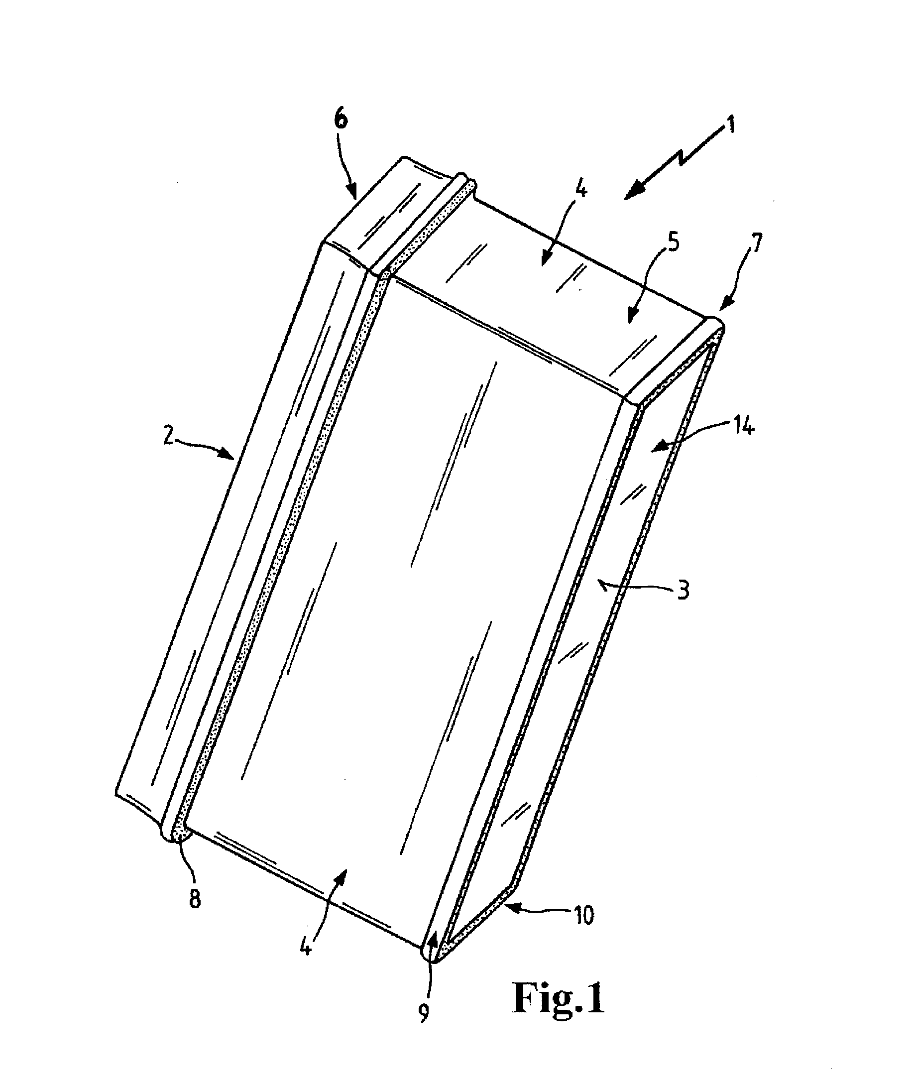
[0110]FIG. 1 shows a filter element 1 with a raw-side inflow side 2 and a clean-side outflow side 3. The filter element is formed by a filter medium 14 that is folded multiple times wherein the folds extend between the inflow side and the outflow sides, i.e., fold tips are positioned at the inflow side and at the outflow side, respectively. The lateral surfaces of the filter element 4 that are not flowed through are enclosed by a polyester nonwoven that is provided on the side that is facing the filter element with a hotmelt layer. This hotmelt layer provides a flat adhesive connection of the polyester nonwoven with the filter element whereby also the end face 5 of the filter bellows is sealed. The filter element 1 comprises a main frame 6 and an auxiliary frame 7 wherein the main frame supports an axial seal 8 that seals in the direction of the outflow side 3 and is introduced into a groove of the main frame or into a groove between main frame and lateral surfaces 4. The auxiliary ...


PUM

PropertyMeasurementUnit
Timeaaaaaaaaaa
Massaaaaaaaaaa
Adhesivityaaaaaaaaaa

Abstract

A filter includes a filter element (1) having a filter medium (106) pleated in a zigzag manner, with a raw side (105) and a clean side. On the raw side (105) and / or on the clean side of the filter medium (14; 106), a plurality of oblong adhesive sections (122) are disposed along at least two adhesive tracks (101) on the filter medium (106), which run obliquely or perpendicularly to the pleat edges (F) at least in some sections. Each adhesive track (101) having at least one adhesive section (122) and at least one adhesive interruption (107). The adhesive interruptions (107) are offset from each other such that in a medium section (120) the adhesive interruptions (107) do not form a passage (126) that runs continuously parallel to the pleat edges (F).

Description

CROSS REFERENCE TO RELATED APPLICATIONS[0001]This application is US National Stage Entry of international patent application no. PCT / EP2010 / 063131, filed Sep. 7, 2010 designating the United States of America, the entire disclosure of which is incorporated herein by reference. Priority is claimed based on Federal Republic of Germany patent application no. 10 2009 040 202.0, filed Sep. 7, 2009, the entire disclosure of which is incorporated herein by reference.TECHNICAL FIELD[0002]The invention concerns a filter for filtering fluids, in particular gases, in particular intake air, fuel or motor oil, in particular of an internal combustion engine, in particular of a motor vehicle, or ambient air for introduction into venting systems of buildings or vehicles, comprising a filter element with a zigzag-folded filter medium having a raw side and a clean side, wherein at the raw side and / or at the clean side of the filter medium a plurality of elongate adhesive sections along at least two li...

Claims


Application Information

Patent Timeline
IPC IPC(8): B01D27/06B01D46/52
CPCB01D46/521B01D46/523B01D39/14B01D29/016B01D2201/127B01D35/005
Inventor MBADINGA-MOUANDA, GELASEGEHWOLF, KLAUS
Owner MANN HUMMEL GMBH
Why Eureka
Try Eureka