
Novel Solar Panel String Converter Topology

Active Publication Date: 2012-09-06
AMPT
View PDF3 Cites 54 Cited by
  • Summary
  • Abstract
  • Description
  • Claims
  • Application Information

AI Technical Summary

Benefits of technology

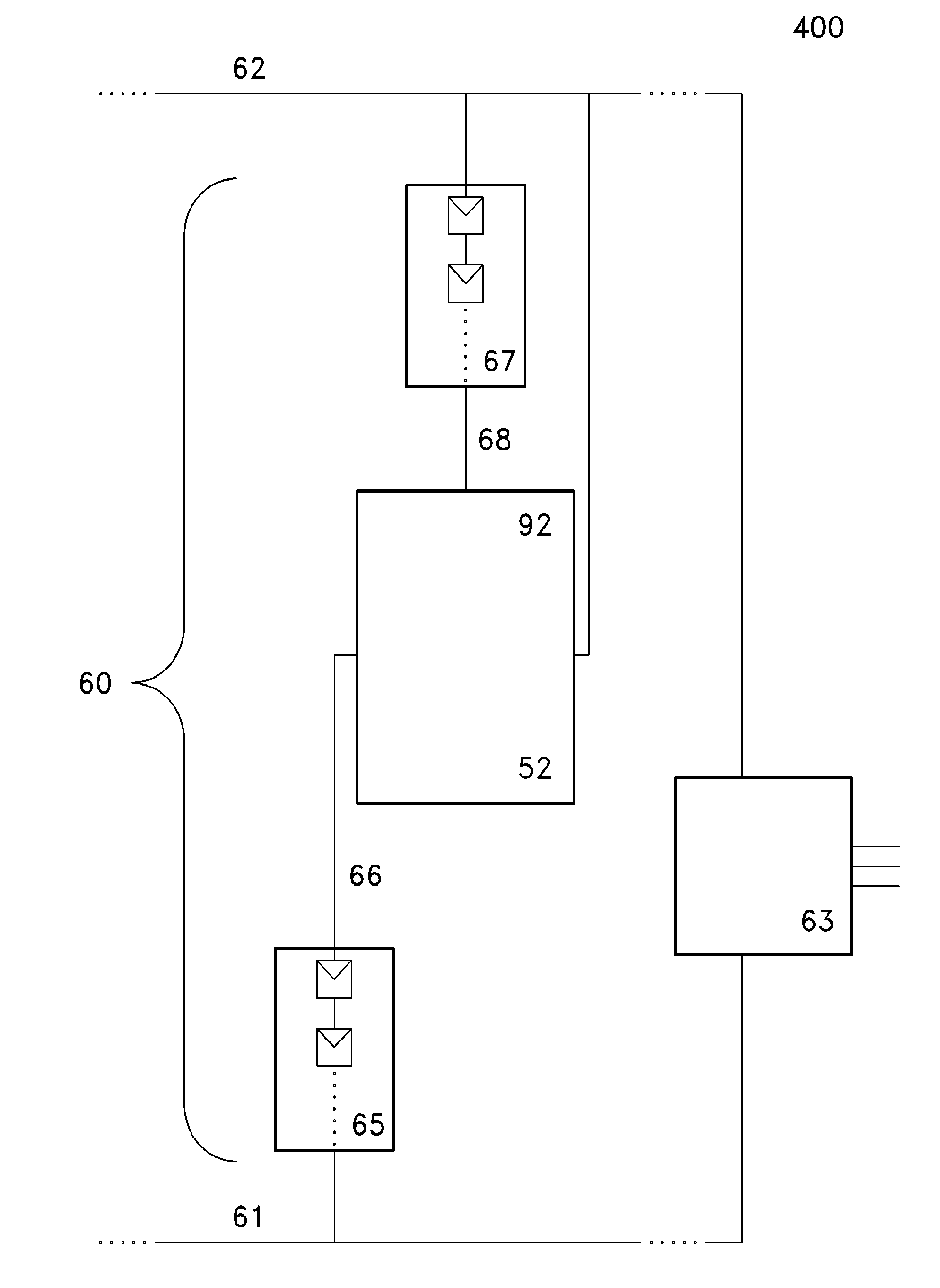
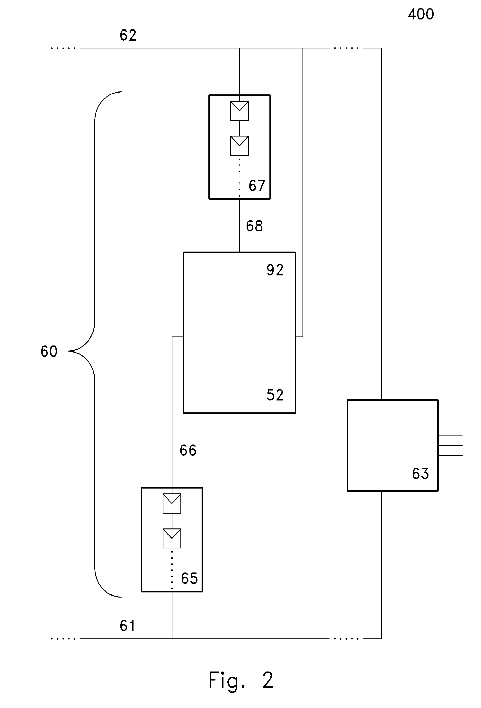
[0013]A novel string DC / DC converter with MPP can be used to solve the third limitation while adding several new benefits. Solving this modules-per-string problem allows a solar PV system designer to place more modules per string (perhaps 2× more) resulting in fewer strings and fewer combiner boxes. The final result can be a lowering of Balance Of System (BOS) cost. As will be seen the architecture disclosed also allows a DC / DC converter to operate at its sweet spot improving efficiency. Another aspect of this invention is the suitability of this architecture for thin film photovoltaic modules in that it can address the low fill factor of thin film technologies with a low cost, highly efficient design.
[0014]One advantage of the inventive technology may be, in embodiments, the ability to place more modules on a string, thereby lowering the total number of strings that a solar array must have to generate a design power. Such reduction of the total number of strings translates into a cost savings, as strings often require expensive componentry (e.g., combiner boxes). In some embodiments, twice as many solar panels may be placed on a string, relative to conventional technologies.

Problems solved by technology

But every module has an individual MPP and an array MPP solution leaves energy unharvested.
Obviously it would not meet the same regulatory limit with a conventional system if more modules were added to this string.
There are a few limitations of string MPP architectures:The harvesting is less compared to MPP / module as current may vary within a string which cannot be corrected.Diagnostic information is only available at the string level instead of module level.During periods when the downstream inverter is not able to deliver power, the string voltage moves to the open circuit voltage of each module added together.

Method used


Image

  • Novel Solar Panel String Converter Topology
  • Novel Solar Panel String Converter Topology
  • Novel Solar Panel String Converter Topology

Examples


Embodiment Construction

[0026]As may be understood from the earlier discussions, the present invention includes a variety of aspects, which may be combined in different ways. The following descriptions are provided to list elements and describe some of the embodiments of the present invention. These elements are listed with initial embodiments, however it should be understood that they may be combined in any manner and in any number to create additional embodiments. The variously described examples and preferred embodiments should not be construed to limit the present invention to only the explicitly described systems, techniques, and applications. Further, this description should be understood to support and encompass descriptions and claims of all the various embodiments, systems, techniques, methods, devices, and applications with any number of the disclosed elements, with each element alone, and also with any and all various permutations and combinations of all elements in this or any subsequent applic...


PUM


Abstract

The inventive technology, in certain embodiments, may be generally described as a solar power generation system with a converter, which may potentially include two or more sub-converters, established intermediately of one or more strings of solar panels. Particular embodiments may involve sweet spot operation in order to achieve improvements in efficiency, and bucking of open circuit voltages by the converter in order that more panels may be placed on an individual string or substring, reducing the number of strings required for a given design, and achieving overall system and array manufacture savings.

Description

CROSS-REFERENCES TO RELATED APPLICATIONS[0001]This is an international patent application and claims priority to U.S. Provisional App. No. 61 / 253,025, filed Oct. 19, 2010, the provisional application incorporated herein in its entirety.TECHNICAL FIELD[0002]This invention relates to methods and apparatus involving grid- or electrical power network-tied photovoltaic (PV) converters. In one embodiment, it especially relates to multiple panel grid-tied PV converters commonly deployed either commercial or even residential power installations.BACKGROUND[0003]Many common PV converters may have challenges to meet cost and reliability challenges. Such challenges need to be viewed from the perspective of generating their electricity savings for payback of initial investment over longer periods. The present invention provides systems that may in some embodiments address cost and reliability goals for many PV systems.[0004]At the current time the use of PV (photovoltaic) panels to generate elec...

Claims


Application Information

Patent Timeline
IPC IPC(8): H02J1/10
CPCH01L31/02021Y02E10/563H02M3/155H02J3/383G05F1/67H02J2300/24H02J3/381H02J2300/26H02J3/46H02S40/32H02S40/36H02J3/38Y02E10/56H02J3/388H02M3/08H02M7/44
Inventor LEDENEV, ANATOLI
Owner AMPT
Learn More