Flat light, in particular for aircraft cabins

Inactive Publication Date: 2012-09-06
DIEHL AEROSPACE GMBH
View PDF5 Cites 18 Cited by
  • Summary
  • Abstract
  • Description
  • Claims
  • Application Information

AI Technical Summary

Benefits of technology

[0037]In one embodiment of the interior furniture element, the light source is arranged laterally with respect to the light mixing chamber, and the light source is covered on the visible side by a cover shade. In particular, the light source, particularly the one or more lighting means, may be covered on the visible side, i.e. as seen from the passenger or transport compartment, by a cover shade extending as far as the light exit side of the flat light. In this case, the cover shade and the flat light may form an essentially continuous contour. This facilitates cleaning of the aircraft cabin. In contrast to conventional indirect illumination of an aircraft cabin, in which a slot for the light to emerge

Problems solved by technology

However, the known flat lights are only limitedly suit

Method used


Image

  • Flat light, in particular for aircraft cabins
  • Flat light, in particular for aircraft cabins
  • Flat light, in particular for aircraft cabins

Examples


Example

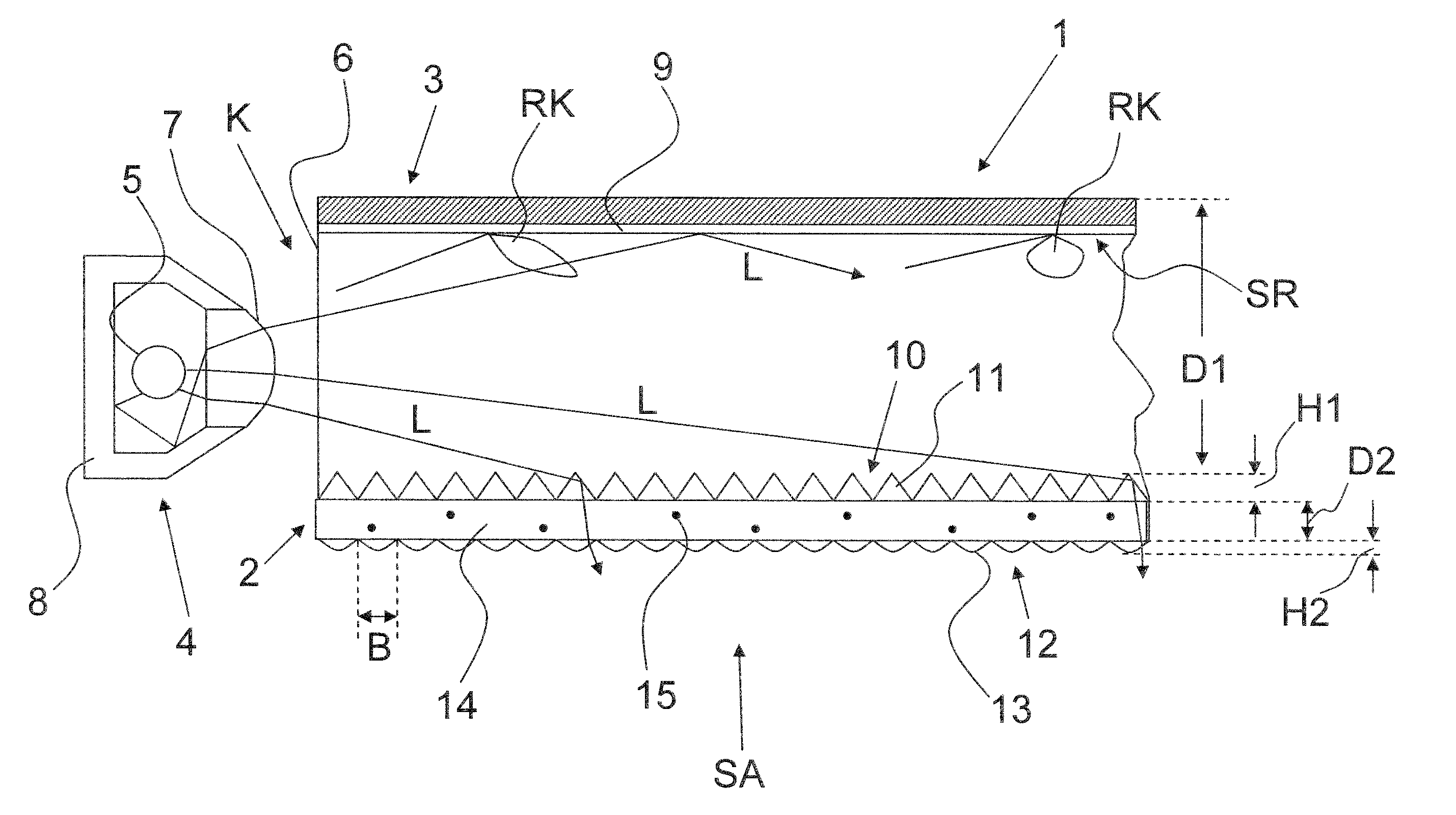
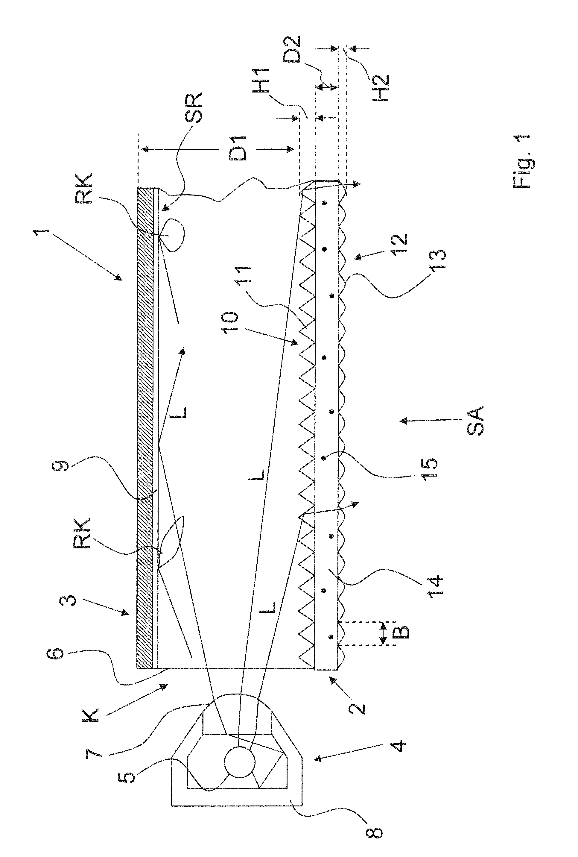
[0042]FIG. 1 shows a partial view through a flat light. The flat light comprises a light box 1 having a light-transmissive front wall 2 arranged on a light exit side SA. The flat light furthermore comprises a rear wall 3 formed so as to reflect in the direction of the front wall 2. The front wall 2 and the rear wall 3 may for example be made of a plastic, in particular PMMA. A light reflection side of the rear wall 3 is denoted by the reference symbol SR. A side edge of the flat light is denoted by the reference symbol K. A first thickness D1 of the flat light may be from 30 to 60 mm.

[0043]A light source 4 comprising a multiplicity of light-emitting diodes 5 arranged in an array, in particular a linear array, is arranged on the side edge K so that the light L generated by the light-emitting diodes can be coupled into the light box 1 through the side edge K, in particular a light entry window 6 provided on the side edge K. The light-emitting diodes may for example be arranged in rows...


PUM


Abstract

The invention relates to a flat light F, in particular for aircraft cabins, comprising a light box 1 and a light source, the light of which is coupled into the light box 1, wherein a rear wall of the light box 1 is formed to be reflective and the front wall of the light box 1 comprises optical elements for directional emission of light.

Description

BACKGROUND OF THE INVENTION[0001]The invention relates to a flat light, in particular for aircraft cabins.DISCUSSION OF THE PRIOR ART[0002]According to the prior art, particularly in advertising as information panels, flat lights are used in which a light guide plate produced from a transparent plastic is provided with a lighting means for shining light in on at least one of its edges. Because of the total internal reflection on the two mutually opposite surfaces of the light guide plate, the volume of the light guide plate is illuminated substantially homogeneously.[0003]However, the known flat lights are only limitedly suitable as illumination elements for e.g. aircraft cabins.SUMMARY OF THIS INVENTION[0004]It is in particular an object of the invention to provide an alternative flat light, in particular one which is as lightweight as possible, which is suitable as illumination particularly in aircraft cabins.[0005]This object is achieved by the features of the independent claims....

Claims


Application Information

Patent Timeline
IPC IPC(8): B64D47/02
CPCB60Q3/025G02B6/0038B64D2011/0038G02B6/0053G02B6/0051B60Q3/64B60Q3/43
Inventor PETERSOHN, JANSAUER, CATHARINABRINKMANN, MATTHIASBACHMAIER, STEFFEN
Owner DIEHL AEROSPACE GMBH
Why Eureka
Try Eureka