Rotary vane compressor

a compressor and rotary vane technology, applied in machines/engines, liquid fuel engines, positive displacement liquid engines, etc., can solve the problems of increasing assembly man-hours and thereby their costs, complex working processes of the vanes, and coil spring application

Inactive Publication Date: 2012-09-06
CALSONIC KANSEI CORP
View PDF7 Cites 7 Cited by
  • Summary
  • Abstract
  • Description
  • Claims
  • Application Information

AI Technical Summary

Benefits of technology

[0014]If the reverse rotational speed is more than 10 rpm, the vane contacts with an inner wall surface near an ellipsoidal edge valley be

Problems solved by technology

In addition, application of the coil springs increases assembling man-hours and thereby its costs.
Fu

Method used


Image

  • Rotary vane compressor
  • Rotary vane compressor
  • Rotary vane compressor

Examples


first embodiment

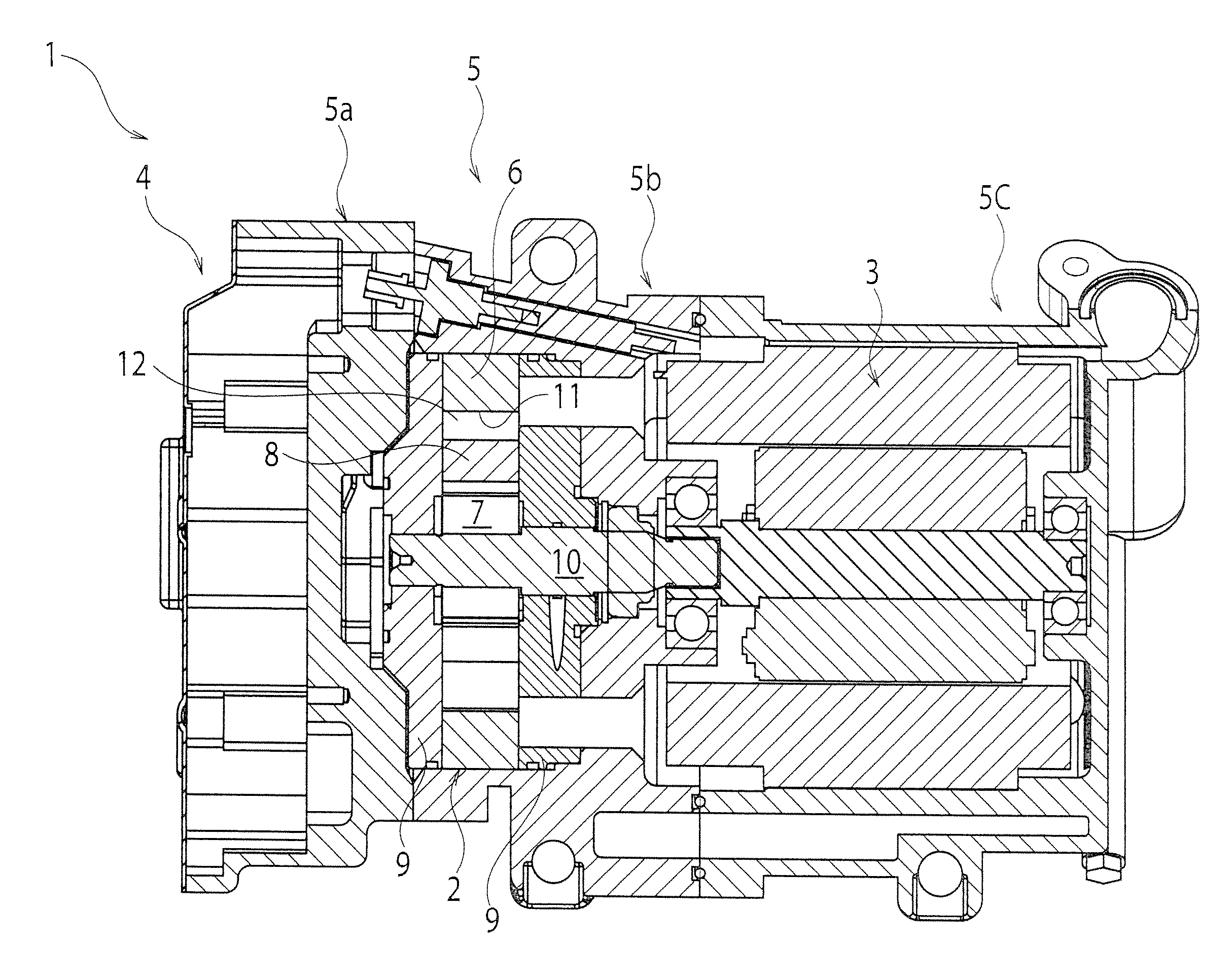
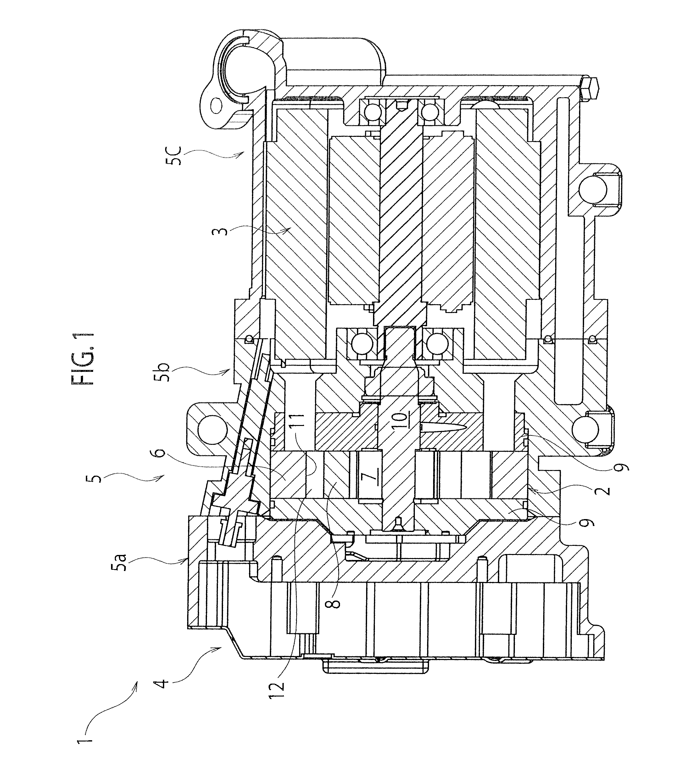
[0022]As shown in FIGS. 1 and 4, a rotary vane compressor 1 according to the present embodiment includes, as its main components, a compression mechanism 2, electrical motor 3, an inverter 4, and a controller 15 for controlling the electrical motor 3 via the inverter 4. A housing 5 of the compressor 1 is comprised of a front housing 5a, a middle housing 5b and a rear housing 5c. An internal space sealed in the inside of the housing 5 by coupling these housings 5a to 5c with each other, and the compression mechanism 2 and the electrical motor 3 are housed in the internal space. The internal space is segmented by the compression mechanism 2, so that a suction chamber for refrigerant is provided on one side of the compression mechanism 2 (on a left side in FIG. 1) and a discharge chamber for refrigerant is provided on another side (on a right side in FIG. 1). The electrical motor 3 is provided in the discharge chamber for refrigerant.

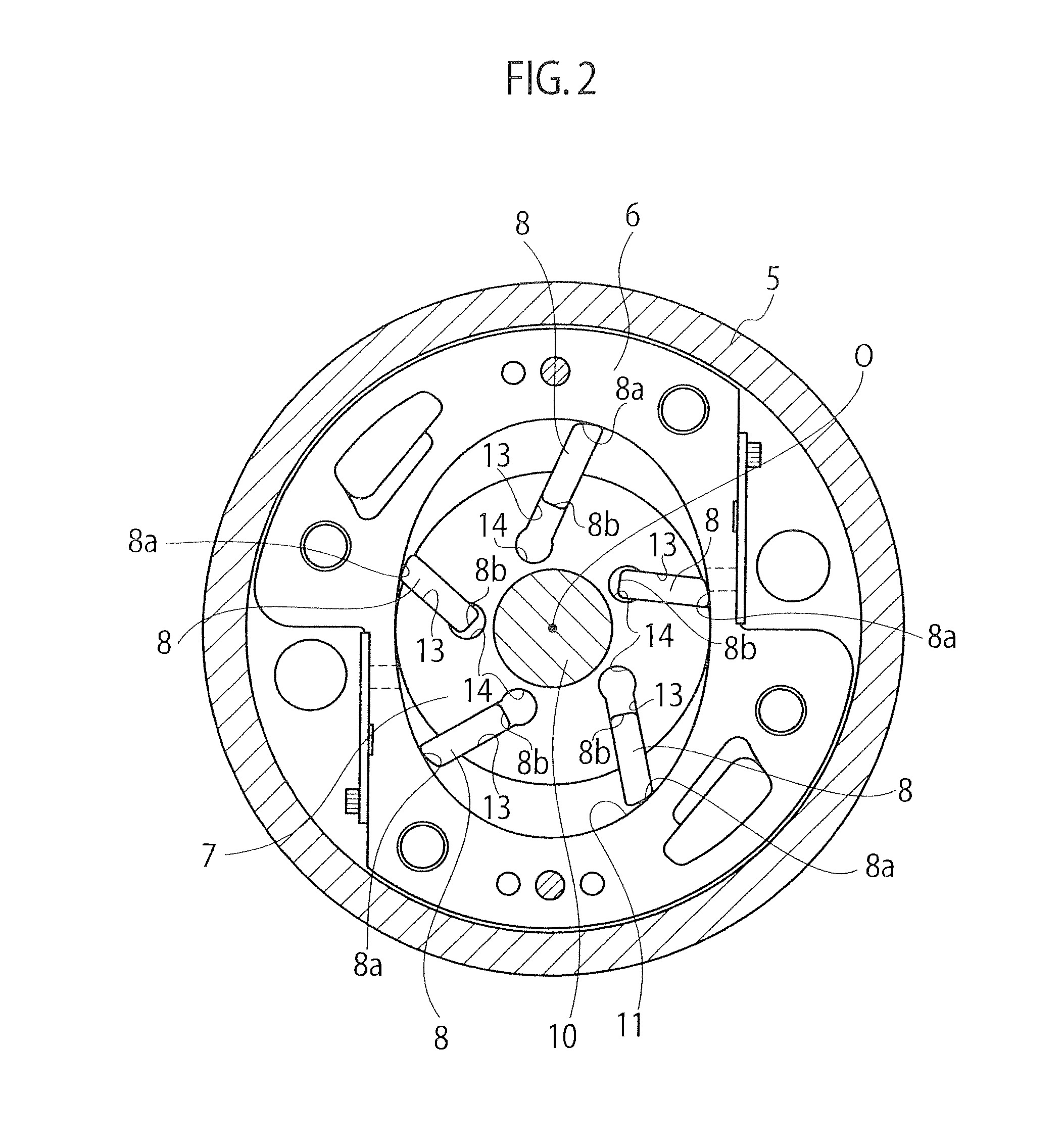
[0023]As shown in FIG. 2, the compression mechanism ...

second embodiment

[0035]Next, a compressor 1 according to a second embodiment will be explained with reference to FIG. 6.

[0036]In the above-explained first embodiment, the controller 15 controls the electrical motor 3 as a drive source of the compression mechanism 2 to normally / reversely rotate the rotor 7. In the present embodiment, the controller 15 controls a gear mechanism 31 to normally / reversely rotate the rotor 7.

[0037]As shown in FIG. 6, the gear mechanism 31 includes a normal rotation rotary shaft 32 and a reverse rotation rotary shaft 33 that are rotated by a rotational drive force form a drive source 30, a normal rotation gear set 34 provided on the normal rotation rotary shaft 32, and a reverse rotation gear set 35 provided on the reverse rotation rotary shaft 33.

[0038]The normal rotation gear set 34 has a normal rotation first gear 34a and a normal rotation second gear 34b, and coupled with the compression mechanism 2 via these gears 34a and 34b. The reverse rotation gear set 35 has a re...


PUM


Abstract

A rotary vane compressor includes a cylinder chamber having an ellipsoidal inner wall shape, a rotor rotatably provided in the cylinder chamber, a vane held in the rotor so as to contact with an inner wall surface of the cylinder chamber along with a rotation of the rotor, a vane slot provided on the rotor and offset on a reverse rotational side of the rotor from a radial line passing over a rotational center of the rotor, and a controller for controlling a rotation of the rotor. The controller reversely rotates the rotor for a predetermined time upon activating the compressor. According to the compressor, chattering can be prevented by surely protruding the vane from the vane slot without providing extra parts. In addition, the vane can be produced with easy working processes at low cost.

Description

TECHNICAL FIELD[0001]The present invention relates to a rotary vane compressor.BACKGROUND ART[0002]In a conventional rotary vane compressor, an intermediate pressure is introduced into backpressure spaces of vanes during operations, so that the vanes are protruded from vane slots. In addition, after stopped, since a pressure in the compressor becomes uniform, forces for protruding the vanes due to the intermediate pressure are not applied. Therefore, a vane whose end edge is directed upward becomes accommodated into a vane slot while lubrication oil in the vane slot is discharged through clearances due to its own weight. When the compressor is activated from the above state, centrifugal forces apply to the vanes so as to protrude them from the vane slots. Volume increase of the backpressure spaces is needed for a vane to protrude from a vane slot, but a lubrication oil amount introduced to the backpressure spaces through the clearances cannot follow and thereby the backpressure spac...

Claims


Application Information

Patent Timeline
IPC IPC(8): F04C18/00F04C23/02
CPCF04C18/3446F04C29/06F04C28/06F04C28/08F04C2270/701F01C21/0863F04C28/04
Inventor SHIMAGUCHI, HIROTADAKUBO, TAKASHITERAZAWA, JUNICHIROU
Owner CALSONIC KANSEI CORP
Why Eureka
Try Eureka