Coaxial cable connector having electrical continuity member

a technology of electrical continuity and coaxial cable, which is applied in the direction of coupling device connection, coupling/disconnecting parts, electrical apparatus, etc., can solve the problems of improper tightening or otherwise installing the connector to the interface por

Active Publication Date: 2012-09-06
PPC BROADBAND INC
View PDF4 Cites 85 Cited by
  • Summary
  • Abstract
  • Description
  • Claims
  • Application Information

AI Technical Summary

Problems solved by technology

However, often connectors are not properly tightened or otherwise installed to the inter...

Method used


Image

  • Coaxial cable connector having electrical continuity member
  • Coaxial cable connector having electrical continuity member
  • Coaxial cable connector having electrical continuity member

Examples


embodiment 1000

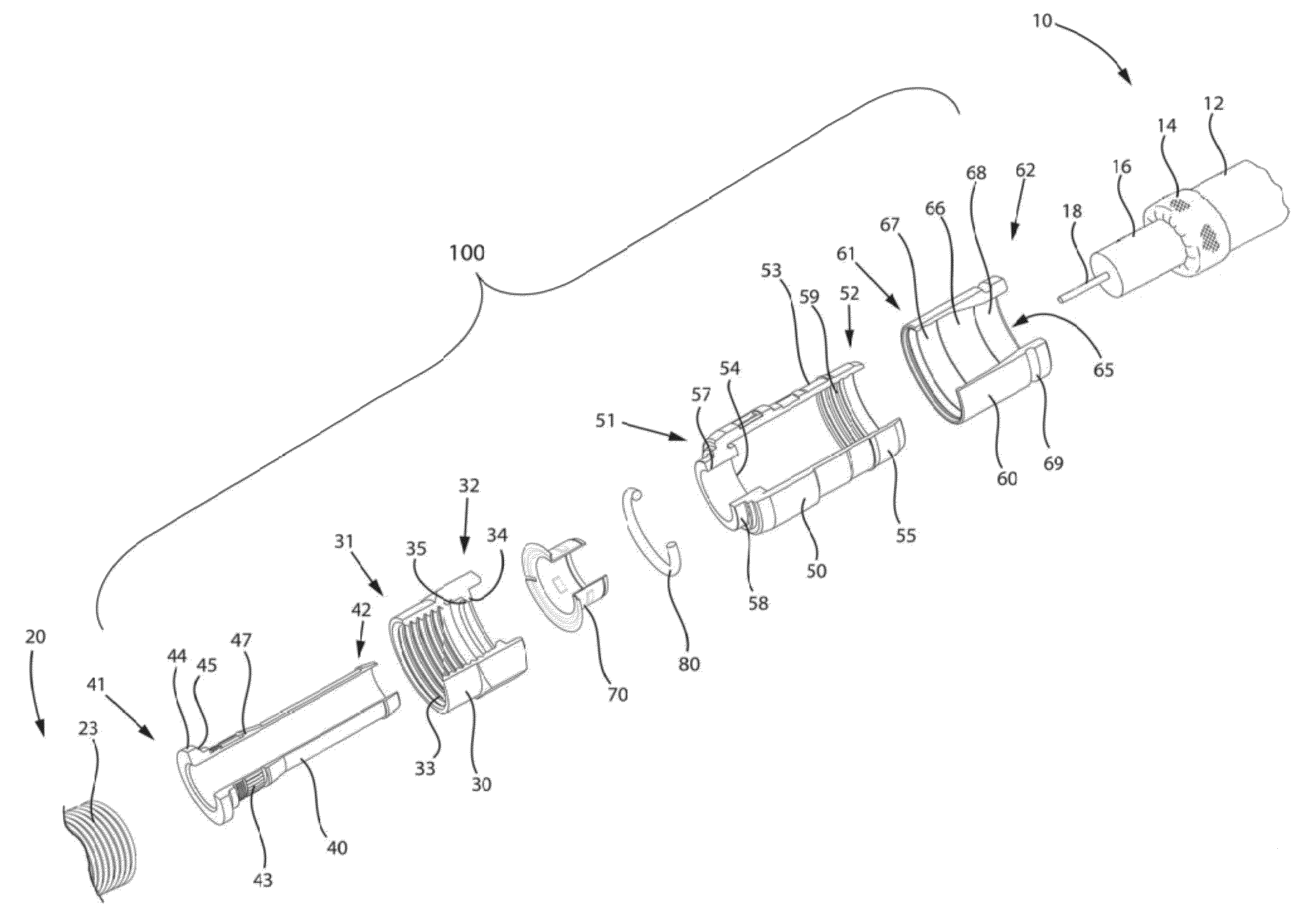
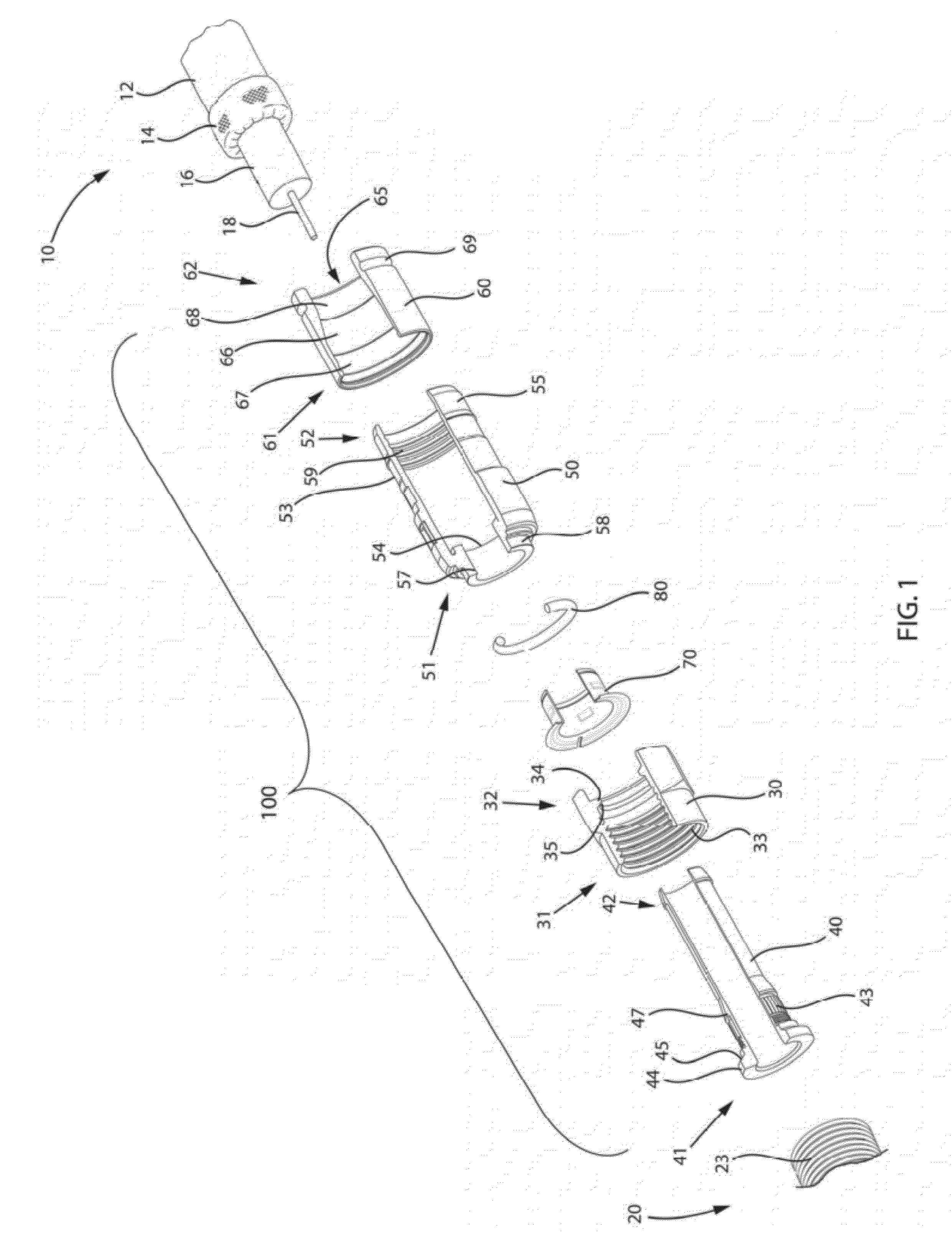
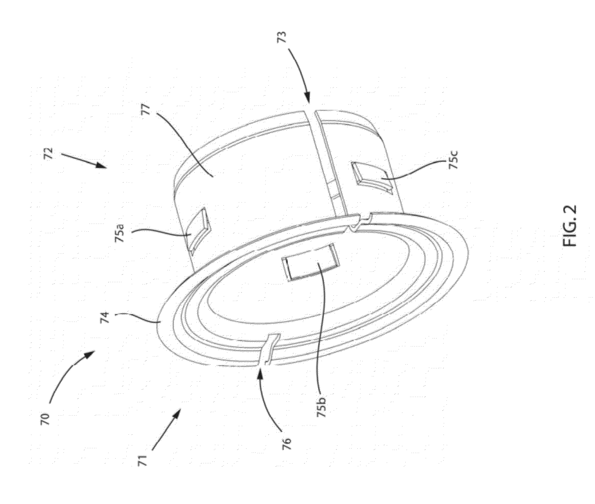
[0086]Turning further to the drawings, FIGS. 33-38 depict yet another embodiment of an electrical continuity member 1070. The electrical continuity member 1070 is operably included, to help facilitate electrical continuity in an embodiment of a coaxial cable connector 1000 having multiple component features, such as a coupling nut 1030, an inner post 1040, a connector body 1050, and a sealing member 1080, along with other like features, wherein such component features are, for the purposes of description herein, structured similarly to corresponding structures (referenced numerically in a similar manner) of other coaxial cable connector embodiments previously discussed herein above, in accordance with the present invention. The electrical continuity member 1070 has a first end 1071 and opposing second end 1072, and includes at least one flexible portion 1079 associated with a nut contact portion 1074. The nut contact portion 1074 may include a nut contact tab 1078. As depicted, an e...

embodiment 1200

[0105]A case study C helped determine the impact of continuous shield continuity connectors, such as connectors 100 / 900 / 1000 / 1100 / 1200, on repeat service calls. The study was designed to evaluate the effect of replacing industry standard (e.g. traditional noncompensating connectors) with continuous shielding continuity connectors, such as connector embodiment 1200 in particular, during routine indoor and outdoor installations. The performance parameter measured in this study was the occurrence rate of repeat service calls. This case study C covered an entire system comprised of seven distinct service groups. The data was collected for 3 months prior to implementing continuous shielding continuity connectors and for 3 months following the implementation. All installation practices remained constant except for exchanging the type of connector used. The data collected for the entire system was combined and analyzed. As depicted in FIG. 59, the results were a drop from 13.7% to 12.5% or...


PUM


Abstract

A coaxial connector comprising a connector body; a nut, axially rotatable with respect to the connector body, the nut having a first forward end configured for threadably attaching to an interface port and a second rearward end; and a continuity member, electrically contacting the nut; wherein the connector is configured to maintain return loss below -40 dBvM when the connector is installed on the interface port, so as to be only engaged with one thread of the interface port is provided.

Description

CROSS-REFERENCE TO RELATED APPLICATIONS[0001]This continuation application claims the priority benefit of U.S. Non-Provisional patent application Ser. No. 12 / 633,792 filed on Dec. 8, 2009, and entitled COAXIAL CABLE CONNECTOR HAVING ELECTRICAL CONTINUITY MEMBER, which claims the priority benefit of U.S. Provisional Patent Application No. 61 / 180,835 filed on May 22, 2009, and entitled COAXIAL CABLE CONNECTOR HAVING ELECTRICAL CONTINUITY MEMBER.FIELD OF THE INVENTION[0002]The present invention relates to connectors used in coaxial cable communication applications, and more specifically to coaxial connectors having electrical continuity members that extend continuity of an electromagnetic interference shield from the cable and through the connector.BACKGROUND OF THE INVENTION[0003]Broadband communications have become an increasingly prevalent form of electromagnetic information exchange and coaxial cables are common conduits for transmission of broadband communications. Coaxial cables ...

Claims


Application Information

Patent Timeline
IPC IPC(8): H01R9/05
CPCH01R9/0524H01R13/622H01R13/6592H01R13/6473H01R13/6584H01R2103/00H01R4/48
Inventor AMIDON, JEREMYLAWRENCE, MICHAEL E.MONTENA, NOAHPURDY, ERIC
Owner PPC BROADBAND INC
Why Eureka
Try Eureka