Systems and methods for distributed sensor clusters

Inactive Publication Date: 2012-09-13
RAYTHEON BBN TECH CORP
View PDF2 Cites 1 Cited by
  • Summary
  • Abstract
  • Description
  • Claims
  • Application Information

AI Technical Summary

Benefits of technology

[0004]In certain vehicles, however, the location of the sensors is constrained by the configuration of the vehicle—external or internal—itself. For instance, in some aircraft, the wire harnesses that could allow transmission of sensor outputs to the aircraft avionics system are pre-determined and fixed at certain hull mounting points (also referred to as “wiring access points” or “hull access points”) and thus, only traverse certain parts of the aircraft. Furthermore, the communication bandwidth of these wire transmissions is generally limited, further constraining the number of sensors that the aircraft will accommodate. In particular, because of the speed at which a projectile approaches and traverses a sensor affixed on the aircraft, a large number (e.g., 2048 or 4092) samples must be recorded by the sensor and processed by a processor to determine a shooter location. For instance, if the processor is l

Problems solved by technology

Furthermore, the communication bandwidth of these wire transmissions is generally limited, further constraining the number of sensors that the aircraft will accommodate.
For instance, if the processor is located in the cockpit of the aircraft or in some location that is physically separated from the sensors, which are generally located at or near hull mounting points or wiring access points, and the limited bandwidth (i.e., high-fidelity signal carrying capacity) of the wiring between these two locations, it is difficult to send all the recorded samples for a

Method used


Image

  • Systems and methods for distributed sensor clusters
  • Systems and methods for distributed sensor clusters
  • Systems and methods for distributed sensor clusters

Examples


Example

[0037]To provide an overall understanding of the invention, certain illustrative embodiments will now be described, including display apparatus and constituent components thereof. However, it will be understood by one of ordinary skill in the art that the apparatus described herein may be adapted and modified as is appropriate for the application being addressed and that the systems and methods described herein may be employed in other suitable applications, and that such other additions and modifications will not depart from the scope hereof.

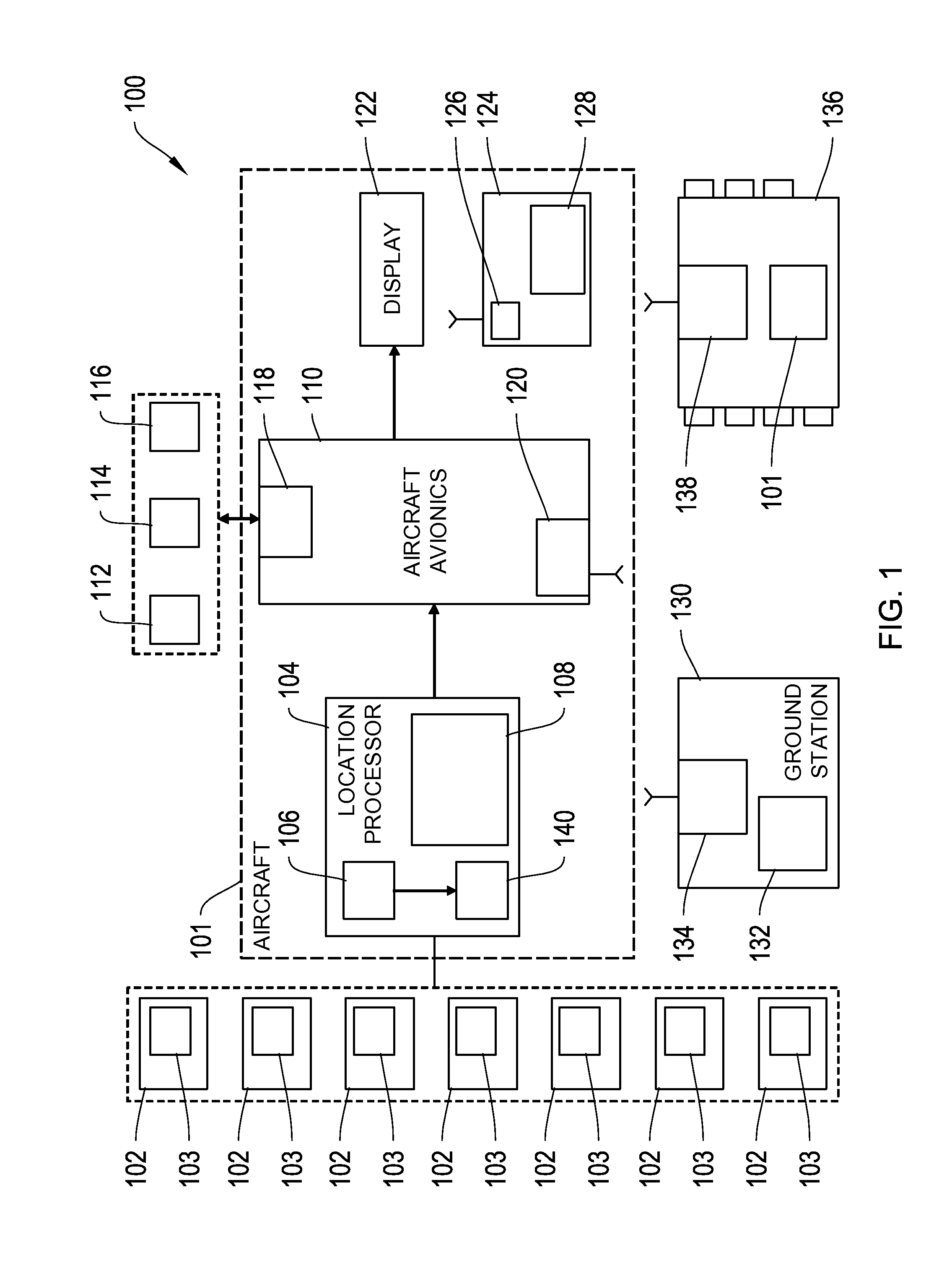
[0038]In this application, embodiments will be described primarily in terms of sensors mounted to the exterior of an aircraft such as a helicopter, however, it will be apparent to those skilled in the art that the systems and methods described herein may also be used in ground vehicle or building applications. Those skilled in the art will come to realize that the synchronization of the timing information described herein with respect to sensor...


PUM


Abstract

Systems and methods for processing signals received from at least two sources are described. The two sources may each include an array of sensors. The sensor arrays may be spaced apart on the surface of a body, such as an aircraft, a ground vehicle, or a building. The sensors are configured for receiving signals from the at least two sources indicative of timing information. The timing information may be associated with a shockwave of a projectile and a location processor configured for determining shooter location based on signals output by each of the at least two arrays of sensors is coupled to each of the at least two arrays of sensors. The location processor is configured to compute global time metrics and local reference times associated with each of the sensors and determine shooter location based on a relationship between computed global time metrics and local reference times.

Description

FIELD OF THE INVENTION[0001]This invention relates generally to security systems, and more particularly to systems and methods for using distributed sensor clusters to detect the origin and path of supersonic projectiles fired at a military vehicle. This invention also relates to methods for synchronizing the timing information associated with signals received from at least two sources, each of which may include a cluster of sensors.BACKGROUND[0002]With recent developments in weapons technology combined with an evolving face of global terrorism, there has been an increase in the threat posed to military personnel in combat, rescue and humanitarian missions in urban settings (e.g., door-to-door warfare), aircraft (e.g., helicopters) and ground vehicles (e.g., Humvees). For example, terrorist militiamen are using inexpensive, portable and readily available weapons such as sniper rifles and shoulder-fired missiles against ground vehicles, low flying aircraft such as helicopters and air...

Claims


Application Information

Patent Timeline
IPC IPC(8): G01S3/80
CPCG01S5/22
Inventor BRINN, MARSHALL SETHMILLIGAN, STEPHEN D.
Owner RAYTHEON BBN TECH CORP
Why Eureka
Try Eureka