
Base station, network system, and implementation method

a network system and base station technology, applied in the field of communication technology, can solve the problems of bbus not being able to effectively share resources, the conventional base station architecture and deployment mode will hardly adapt to these changes, and the number and standards of base stations, so as to enhance the degree of resource sharing in the base station

Active Publication Date: 2012-09-13
HUAWEI TECH CO LTD
View PDF11 Cites 18 Cited by
  • Summary
  • Abstract
  • Description
  • Claims
  • Application Information

AI Technical Summary

Benefits of technology

The present invention provides a base station with a central node and multiple edge nodes that communicate with users and execute baseband processing and mutual conversion between baseband data and radio data. The edge nodes belong to groups, and the central node manages the edge nodes and performs resource sharing so that resources are shared by the multiple edge nodes. This enhances the resource sharing degree in the base station. The invention also provides a method for managing the base station and a network system with the base station. The technical effects of the invention are improved resource sharing and efficient management of the base station.

Problems solved by technology

However, due to the factors of market policy and network maturity, these standards will coexist for a long time, which brings new challenges to the design of base station architecture and the operation and maintenance management of base stations.
Additionally, the rapid growth for mobile bandwidth requirements in hot spot regions greatly increases the number and standards of base stations in these hot spot regions, and the conventional base station architecture and deployment mode will hardly adapt to these changes.
The inventors find in the process of implementing the present invention that, due to the deficiencies of the current base station architecture, the BBU Hotel is implemented only in a manner of simply stacking BBUs, and the BBUs are not able to effectively share resources.

Method used


Image

  • Base station, network system, and implementation method
  • Base station, network system, and implementation method
  • Base station, network system, and implementation method

Examples


Embodiment Construction

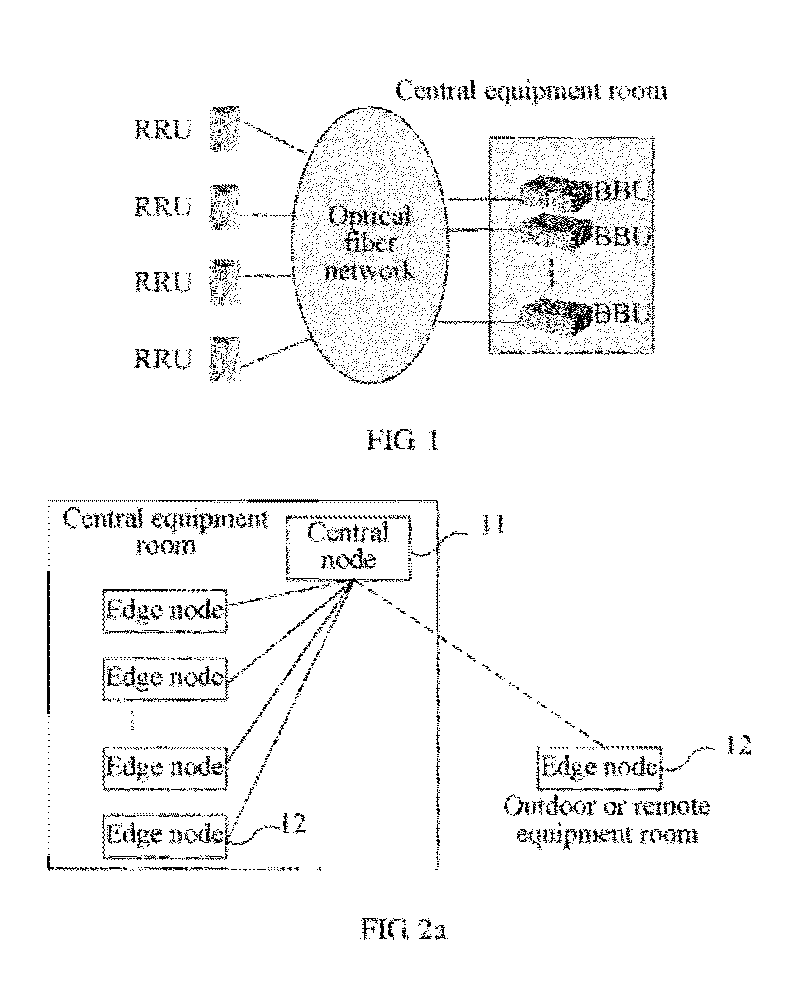
[0024]The inventors find through analysis that, in the BBU Hotel solution, because the BBUs are completely independent from each other and are only simply stacked, resource sharing so that resources are shared by the BBUs cannot be implemented, and it is difficult to perform highly effective exchange of service data among the BBUs. Furthermore, from the angle of network management, the BBU management granularity (namely, the minimal management object) is also fixed and cannot be flexibly adjusted.

[0025]It can be predicted that multiple communication standards will coexist for a period of time. In a multi-standard base station, if such a BBU Hotel solution is adopted, new problems are further introduced. Because the BBU needs to support multiple standards, for example, the GSM and the UMTS, while different standard boards of a same station are usually placed in a same BBU, the BBU expansion is limited by the physical space. In addition, in a multi-standard base station, the requireme...


PUM


Abstract

A base station includes multiple edge nodes and a central node. The edge nodes are configured to perform communication with a user equipment, and execute baseband processing and mutual conversion between baseband data and radio data, in which the multiple edge nodes belong to one or more edge node groups, and each edge node group includes at least one edge node. The central node is configured to perform communication with the multiple edge nodes, manage the multiple edge nodes, and perform resource sharing so that resources are shared by the multiple edge nodes. The base station is divided into two levels of architecture, namely, a central node and an edge node, and the central node implements resource sharing so that resources are shared by the edge nodes, so that a resource sharing degree in the base station is enhanced.

Description

CROSS-REFERENCE TO RELATED APPLICATIONS[0001]This application is a continuation of International Application No. PCT / CN2010 / 079042, filed on Nov. 24, 2010, which claims priority to Chinese Patent Application No. 200910188422.5, filed on Nov. 24, 2009, both of which are hereby incorporated by reference in their entireties.FIELD OF THE INVENTION[0002]Embodiments of the present invention relate to the communications technology, and in particular, to a base station, a network system, and an implementation method.BACKGROUND OF THE INVENTION[0003]With the rapid development of mobile broadband, the mobile network is going through unprecedented changes. The mobile standard is gradually evolving from the GSM to the UMTS and LTE. However, due to the factors of market policy and network maturity, these standards will coexist for a long time, which brings new challenges to the design of base station architecture and the operation and maintenance management of base stations. Based on the idea of...

Claims


Application Information

Patent Timeline
Patent Type & Authority Applications(United States)
IPC IPC(8): H04W72/04H04W4/00
CPCH04L5/0037H04B7/024H04W88/085H04W28/16H04W88/10
Inventor WU, WANGJUNZHOU, JUNLAN, PENGWANG, ZIQIANGXIA, JUNZHAO, YONGXIANGWANG, JINGYUXIANG, NENGWUMA, NI
Owner HUAWEI TECH CO LTD
Learn More