Methods and apparatuses for encoding and decoding video using adaptive interpolation filter length
a technology of adaptive interpolation and filter length, applied in the field of multimedia data coding, can solve problems such as unsatisfactory large memory bandwidth usage, and achieve the effect of reducing memory bandwidth usag
- Summary
- Abstract
- Description
- Claims
- Application Information
AI Technical Summary
Benefits of technology
Problems solved by technology
Method used
Image
Examples
embodiment 1
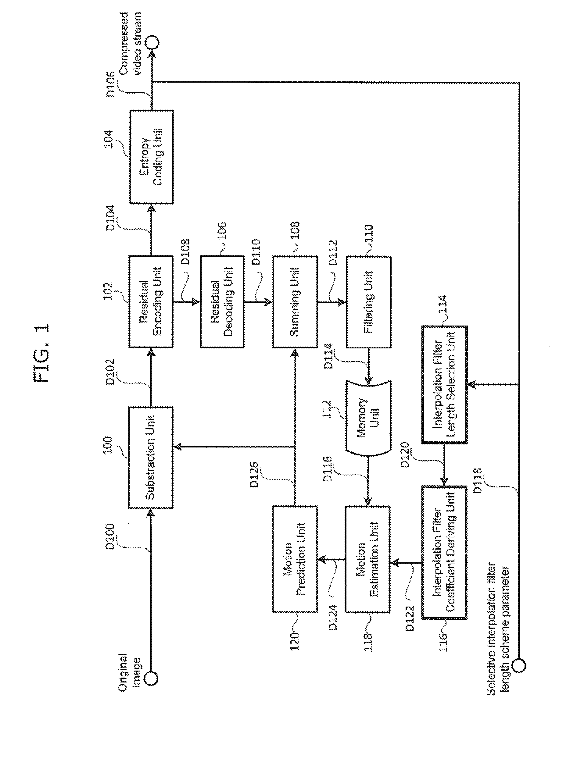
[0072]FIG. 1 shows a block diagram illustrating an example apparatus for a video encoder using current invention. It includes a subtraction unit 100, a residual encoding unit 102, an entropy coding unit 104, a residual decoding unit 106, a summing unit 108, a filtering unit 110, a memory unit 112, an interpolation filter length selection unit 114, an interpolation'filter coefficient deriving unit 116, a motion estimation unit 118, and a motion prediction unit 120.
[0073]As shown in FIG. 1, the subtraction unit 100 takes original samples D100 of the target picture and subtracts with prediction samples D126 to output residual values D102. The residual encoding unit 102 takes the residuals D102 and output compressed residual coefficients D104. The compressed residual coefficients D104 are then entropy coded by the entropy coding unit 104 and outputs into a compressed video D106. The residual decoding unit 106 takes the compressed residual coefficients D108 and outputs decoded residual v...
embodiment 2
[0106]The processing described in each of embodiments can be simply implemented in an independent computer system, by recording, in a recording medium, a program for implementing the configurations of the moving picture coding method (image coding method) and the moving picture decoding method (image decoding method) described in each of embodiments. The recording media may be any recording media as long as the program can be recorded, such as a magnetic disk, an optical disk, a magnetic optical disk, an IC card, and a semiconductor memory.
[0107]Hereinafter, the applications to the moving picture coding method (image coding method) and the moving picture decoding method (image decoding method) described in each of embodiments and systems using thereof will be described. The system has a feature of having an image coding and decoding apparatus that includes an image coding apparatus using the image coding method and an image decoding apparatus using the image decoding method. Other c...
embodiment 3
[0140]Video data can be generated by switching, as necessary, between (i) the moving picture coding method or the moving picture coding apparatus shown in each of embodiments and (ii) a moving picture coding method or a moving picture coding apparatus in conformity with a different standard, such as MPEG-2, MPEG-4 AVC, and VC-1.
[0141]Here, when a plurality of video data that conforms to the different standards is generated and is then decoded, the decoding methods need to be selected to conform to the different standards. However, since to which standard each of the plurality of the video data to be decoded conform cannot be detected, there is a problem that an appropriate decoding method cannot be selected.
[0142]In order to solve the problem, multiplexed data obtained by multiplexing audio data and others onto video data has a structure including identification information indicating to which standard the video data conforms. The specific structure of the multiplexed data including...
PUM
 Abstract
Description
Claims
Application Information
 - R&D
- Intellectual Property
- Life Sciences
- Materials
- Tech Scout
- Unparalleled Data Quality
- Higher Quality Content
- 60% Fewer Hallucinations
Browse by: Latest US Patents, China's latest patents, Technical Efficacy Thesaurus, Application Domain, Technology Topic, Popular Technical Reports.
© 2025 PatSnap. All rights reserved.Legal|Privacy policy|Modern Slavery Act Transparency Statement|Sitemap|About US| Contact US: help@patsnap.com


