Image capture apparatus

an image capture and automatic adjustment technology, applied in the direction of cameras, instruments, printers, etc., can solve the problem of difficulty in continuing to focus on skaters, and achieve the effect of appropriate focus adjustmen

Active Publication Date: 2012-09-20
CANON KK
View PDF3 Cites 48 Cited by
  • Summary
  • Abstract
  • Description
  • Claims
  • Application Information

AI Technical Summary

Benefits of technology

[0008]The present invention makes it possible to continue to appropriately adjust the focus on a main object even if the motion characteristics of the main object change rapidly in an image capture apparatus having an autofocus function.

Problems solved by technology

However, when focus detection is performed for, for example, a figure skater, the direction in which he or she moves may change rapidly in the middle of the performance due, for example, to a jump or fall, so it is difficult to continue to focus on the skater.

Method used


Image

  • Image capture apparatus
  • Image capture apparatus
  • Image capture apparatus

Examples


first embodiment

[0024]

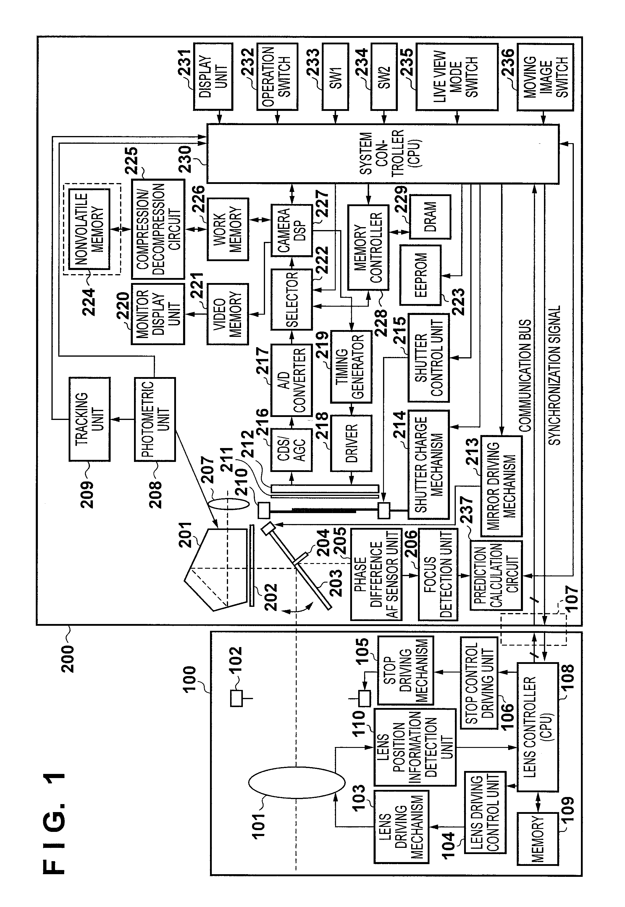
[0025]FIG. 1 is a block diagram showing the configuration of a digital camera according to the first embodiment of an image capture apparatus of the present invention. An imaging lens 100 is detachably mounted on a digital camera 200 via a lens mounting mechanism in a mount portion (not shown), as shown in FIG. 1. The mount portion is provided with an electric contact unit 107. The electric contact unit 107 has a terminal for a communication bus line including, for example, a communication clock line, a data transfer line, a data reception line. These lines allow the digital camera 200 and the imaging lens 100 to communicate with each other. The digital camera 200 communicates with the imaging lens 100 via the electric contact unit 107 to control driving of a focus lens 101 and a stop 102 which adjusts the amount of incident light, in the imaging lens 100. Although FIG. 1 shows only the focus lens 101 as a lens in the imaging lens 100, a scaling lens and a fixed lens are also ...

modification to first embodiment

[0076]In the first embodiment, the tracking unit 209 performs correlation calculation using photometric image data obtained by the previous focus detection operation and that obtained by the first focus detection operation to the past from the previous focus detection operation to detect the direction and amount of movement of the object. However, the present invention is not limited to this, and the image magnification information (image magnification coefficient) of the imaging lens 100 may be output as needed from the lens controller 108 to the tracking unit 209 via the system controller 230, so that the tracking unit 209 performs correlation calculation after scaling the photometric image data based on the image magnification information. This operation makes it possible to improve the correlation calculation accuracy and, in turn, to improve the prediction calculation accuracy, thus more accurately controlling the focus.

[0077]Also, although the prediction calculation circuit 23...

second embodiment

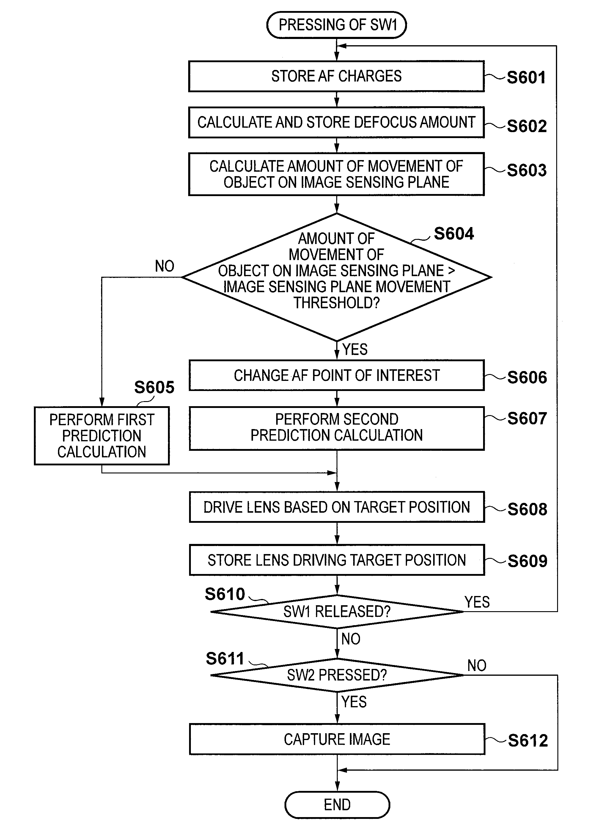
[0078]In the first embodiment, the tracking unit 209 detects movement of the object on the image sensing plane using photometric image data obtained by the photometric unit 208. However, the present invention is not limited to this, and a digital camera 200 may be provided with a gyro to detect an orientation shift of the digital camera 200, thereby performing prediction calculation of the position of the object on the image plane while switching the focus detection region of interest using this orientation shift. When, for example, a professional cameraperson tracks the object, normally, the photographer is regarded as appropriately maintaining the composition, and continues to predict the position of the object on the image plane based on the detected defocus results corresponding to a predetermined number of past focus detection operations in the focus detection region of interest. On the other hand, when the object changes its position on the image sensing plane too rapidly to a...


PUM


Abstract

An image capture apparatus which captures an object image formed by an imaging lens, comprises a focus detection unit which detects a focus position of the object image at a plurality of positions on an image sensing plane, a prediction unit which stores the past output from the focus detection unit, and predicts a locus of the focus position of the object image based on the stored output, thereby predicting the focus position of the object image at a predetermined time instant, a detection unit which detects a shift of the object image on the image sensing plane, and a control unit which changes the output from the prediction unit based on the output from the detection unit.

Description

BACKGROUND OF THE INVENTION[0001]1. Field of the Invention[0002]The present invention relates to an automatic focus adjustment technique in an image capture apparatus.[0003]2. Description of the Related Art[0004]A focus detection apparatus which detects relative movement of a main object, to undergo focus detection, on a two-dimensional image sensing plane based on a change in luminance signal or color difference signal, thereby moving the focus detection position in accordance with the movement of the main object has conventionally been proposed, as described in Japanese Patent Laid-Open No. 60-249477.[0005]A focus detection apparatus which predicts the focus position of a main object a predetermined time into the future based on a temporal change in characteristic of focus detection while continuously performing focus detection of the main object has conventionally been proposed as well, as described in Japanese Patent No. 03218730.[0006]The focus detection apparatus described in ...

Claims


Application Information

Patent Timeline
Patent Type & Authority Applications(United States)
IPC IPC(8): G03B13/36
CPCG02B7/34G03B13/36H04N5/23212H04N23/663H04N23/672H04N23/673H04N23/6811H04N23/6812
Inventor KAWARADA, MASAHIRO
Owner CANON KK
Why Eureka
Try Eureka