Inspection apparatus and its focus adjustment method

Active Publication Date: 2017-09-07
LASERTEC CORP
View PDF4 Cites 7 Cited by
  • Summary
  • Abstract
  • Description
  • Claims
  • Application Information

AI Technical Summary

Benefits of technology

[0022]In the above-described focus adjustment method, the illumination optical system may include a dropping mirror disposed directly above the EUV mask, the dropping mirror being configured to reflect the EUV light emitted from the EUV light source toward the EUV mask, so that the AF light is incident on the EUV mask from outside of the dropping mirror. By the above-described configuration, it is possible to adjust the focus with a simple configuration.
[0023]In the above-described focus adjustment method, an incident place of the AF light may coincide with the incident place of the EUV light in the EUV mask. By the above-described configuration, it is possible to adjust the focus that is located in the same place as an inspection area.
[0024]In the above-described focus adjustment method, the incident place of the AF light may be deviated from the incident place of the EUV light in the EUV mas

Problems solved by technology

Because of this fact, the detection of a

Method used


Image

  • Inspection apparatus and its focus adjustment method
  • Inspection apparatus and its focus adjustment method
  • Inspection apparatus and its focus adjustment method

Examples


first exemplary embodiment

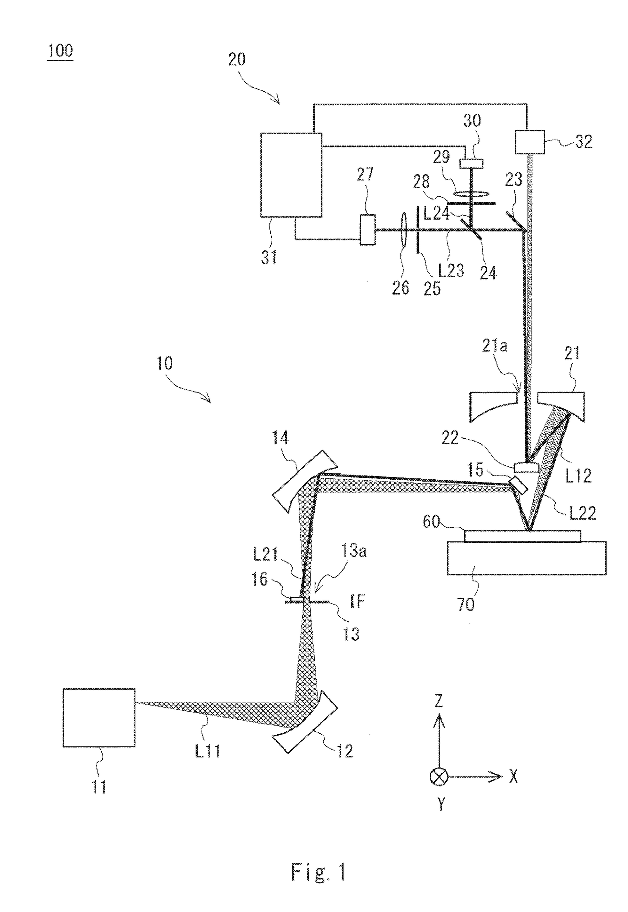
[0032]Exemplary embodiments according to the present invention are explained hereinafter with reference to the drawings. Firstly, an overall configuration of an inspection apparatus according to this exemplary embodiment is explained with reference to FIG. 1. FIG. 1 shows an optical system of an inspection apparatus 100 for inspecting an EUV mask 60.

[0033]The inspection apparatus 100 includes an illumination optical system 10, a detection optical system 20, a processing device 31, a camera 32, and a stage 70. The illumination optical system 10 includes an EUV light source 11, a concave mirror 12, a stop 13, a concave mirror 14, and a dropping mirror 15. The detection optical system 20 includes a concave mirror with a hole formed therein (hereinafter also referred to as a “concave mirror with hole”) 21, a convex mirror 22, a mirror 23, a half mirror 24, a slit 25, a lens 26, a first detector 27, a slit 28, a lens 29, and a second detector 30.

[0034]The inspection apparatus 100 include...

second exemplary embodiment

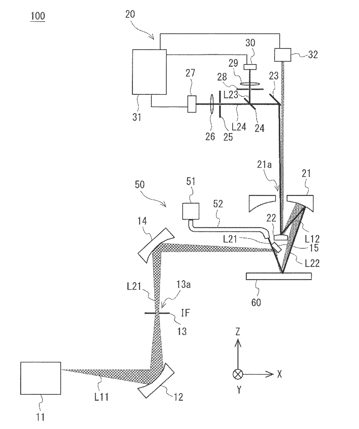
[0064]An inspection apparatus and its focus adjustment method according to this exemplary embodiment are explained with reference to FIG. 5. FIG. 5 shows a configuration of an inspection apparatus according to a second exemplary embodiment. Note that the configuration of the second exemplary embodiment differs from that of the first exemplary embodiment in regard to an AF illumination optical system 50 for applying (i.e., emitting) AF light to the EUV mask 60. Specifically, the AF illumination optical system 50 includes an AF light source 51 and an optical fiber 52 in this exemplary embodiment. That is, the AF light source 51 and the optical fiber 52 are provided in place of the AF light source 16. Note that the configuration other than the AF illumination optical system 50 of the second exemplary embodiment is similar to that of the first exemplary embodiment and therefore its explanation is omitted.

[0065]AF light emitted from the AF light source 51 propagates through the optical f...


PUM


Abstract

An inspection apparatus according to an aspect of the present invention includes an EUV light source 11, an illumination optical system 10 provided to apply the EUV light to an EUV mask 60, a concave mirror and a convex mirror 22 configured to reflect the EUV light reflected on the EUV mask 60, a camera 32 configured to detect EUV light reflected on the convex mirror 22 and thereby take an image of the EUV mask 60, an AF light source 16 configured to generate AF light having a wavelength of 450 nm to 650 nm, first and second detectors 27 and 30 configured to detect the AF light reflected on the EUV mask 60 through the concave mirror with the hole 21 and the convex mirror 22, and an processing device 31 configured to adjust a focus point of the EUV light on the EUV mask 60.

Description

CROSS REFERENCE TO RELATED APPLICATIONS[0001]The present application claims priority to Japanese Patent Application No. 2016-039598, filed on Mar. 2, 2016, the entire contents of which are hereby incorporated by reference in their entirety for all purposes.BACKGROUND OF THE INVENTION[0002]Field of the Invention[0003]The present invention relates to an inspection apparatus for an EUV mask and its focus adjustment method.[0004]Description of Related Art[0005]For a lithography technology that plays an important role in the miniaturization of semiconductor devices, ArF lithography in which an ArF excimer laser having an exposure wavelength of 193 nm is used as an exposure light source is currently used for mass-production. Further, an immersion technique (also called “ArF immersion lithography”) for increasing the resolution of an exposure device by filling a space between its objective lens and a wafer with water has also begun to be used for mass production. In order to advance the mi...

Claims


Application Information

Patent Timeline
IPC IPC(8): G06T7/00G01N21/88H04N5/225G01N21/956
CPCG06T7/0004G01N21/956G01N21/8806G06T2207/10148G06T2207/30148G01N2021/95676H04N5/2256G03F1/84H04N23/56
Inventor MIYAI, HIROKITAKEHISA, KIWAMU
Owner LASERTEC CORP
Why Eureka
Try Eureka