Toner density sensor and image forming apparatus

a technology of density sensor and image forming apparatus, which is applied in the direction of electrographic process apparatus, instruments, optics, etc., can solve the problems of noise generation in the detection voltage of light receiving unit, degradation of detection accuracy, and so as to reduce noise light reaching the light receiving unit, improve the detection accuracy, and reduce the effect of light propagating in the board

Inactive Publication Date: 2012-09-20
ORMON CORP
View PDF3 Cites 15 Cited by
  • Summary
  • Abstract
  • Description
  • Claims
  • Application Information

AI Technical Summary

Benefits of technology

[0013]In the configuration of the toner density sensor, when the penetration space is formed in the portion in which the light emitting unit is attached to the board, the light that is emitted from the light emitting unit to possibly become the noise light radiates to the outside through the penetration space, and the light propagating in the board is reduced. When the penetration space is formed in the portion in which the light receiving unit is attached to the board, the noise light that propagates in the board to reach the light receiving unit is diffused by the inside surface of the penetration space, and the noise light reaching the light re

Problems solved by technology

Therefore, noise light is generated.
The noise light is also called stray light, which causes degradation of the detection accuracy.
As a re

Method used


Image

  • Toner density sensor and image forming apparatus
  • Toner density sensor and image forming apparatus
  • Toner density sensor and image forming apparatus

Examples


Embodiment Construction

[0030]Hereinafter, embodiments of the present invention will be described with reference to the drawings. In embodiments of the invention, numerous specific details are set forth in order to provide a more thorough understanding of the invention. However, it will be apparent to one of ordinary skill in the art that the invention may be practiced without these specific details. In other instances, well-known features have not been described in detail to avoid obscuring the invention.

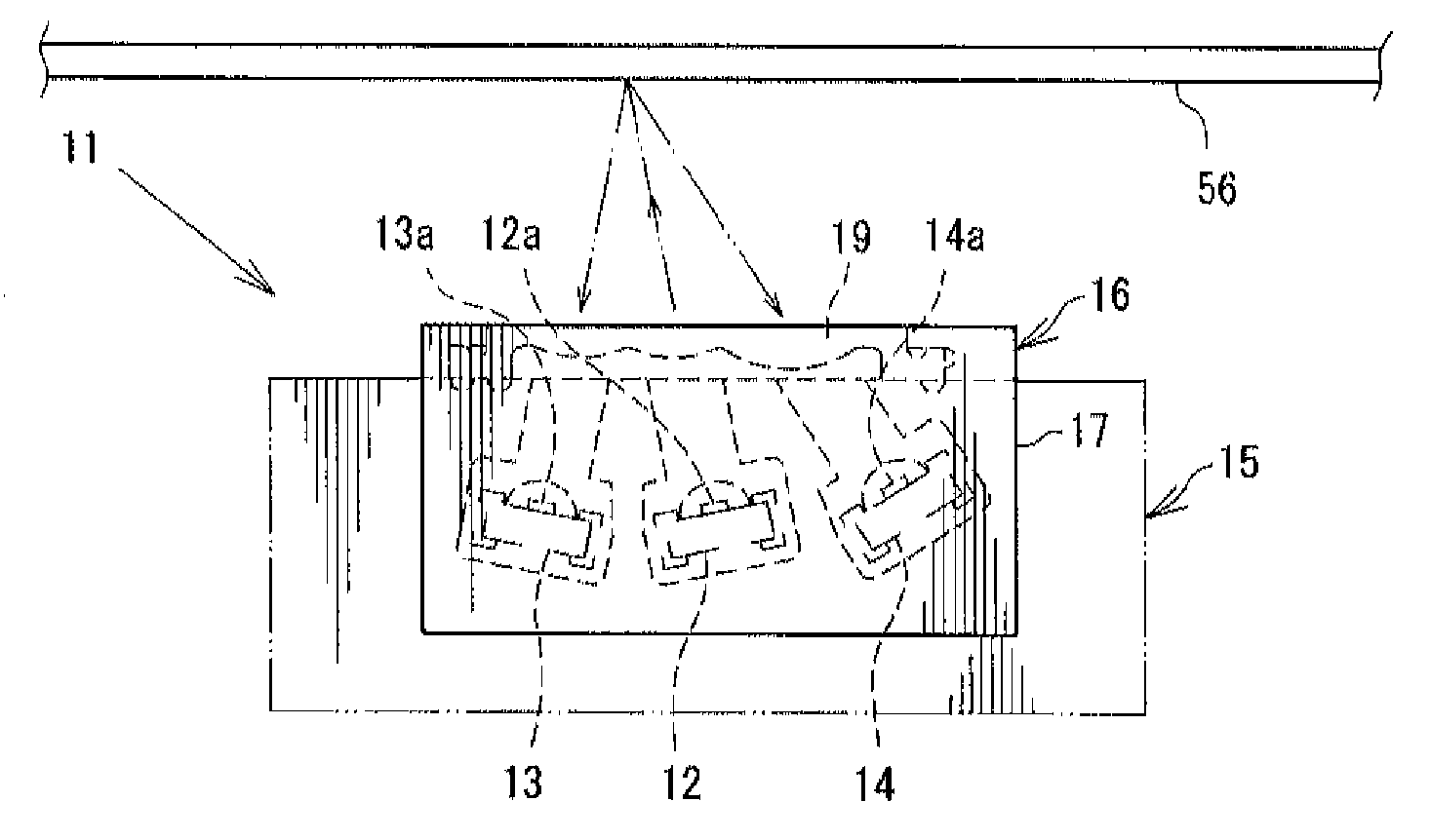
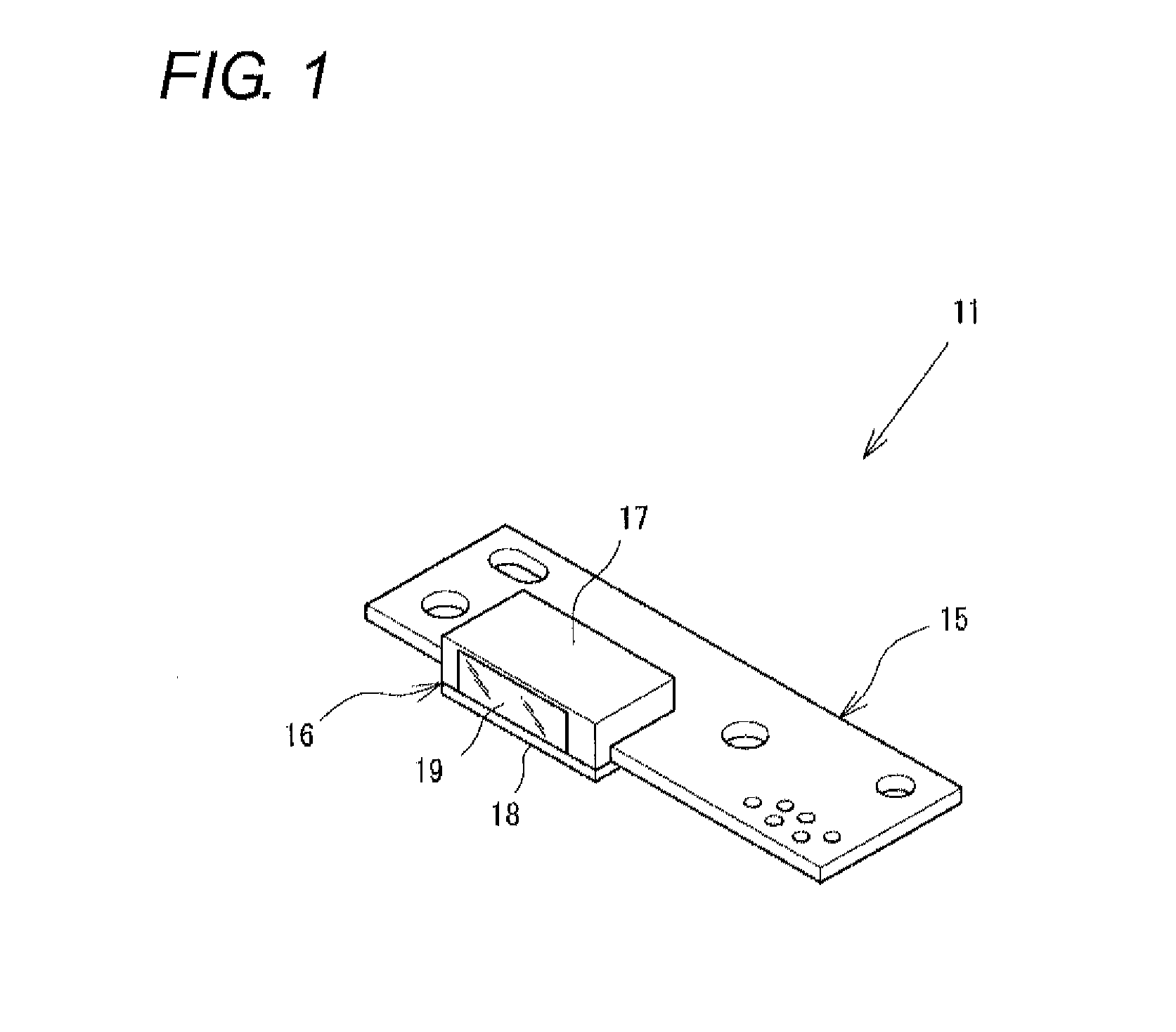
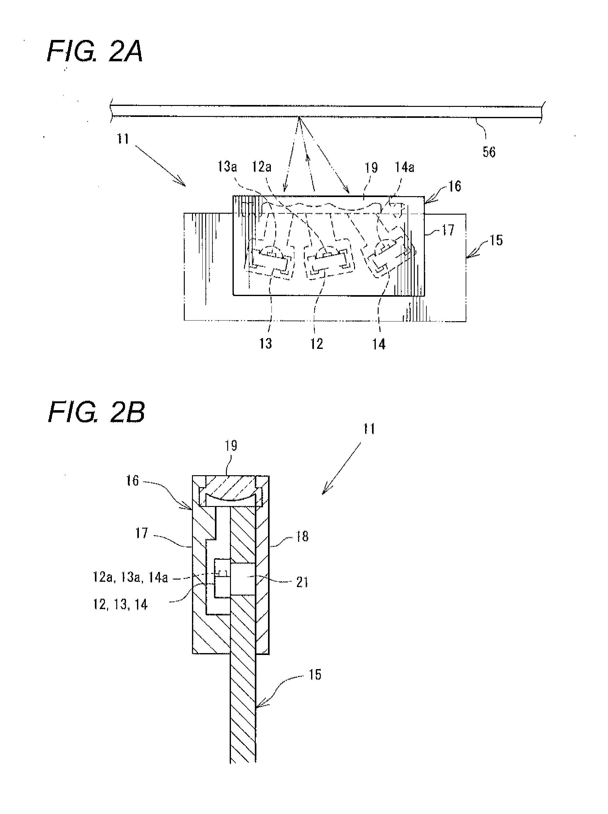
[0031]FIG. 1 is a perspective view of a toner density sensor 11, and FIG. 2 is an explanatory view illustrating a schematic structure of the toner density sensor 11.

[0032]The toner density sensor 11 is mounted on an image forming apparatus 51 illustrated in FIG. 3. For example, the image forming apparatus 51 is a color laser printer. The schematic structure of the image forming apparatus 51 will be described below.

[0033]The image forming apparatus 51 includes an original reading unit 52 that is provided i...


PUM


Abstract

A toner density sensor has a light emitting unit that emits light to detect toner density, a light receiving unit that receives the light emitted from the light emitting unit and reflected from a detection target, and a board on which the light emitting unit and the light receiving unit are surface-mounted. A penetration space that penetrates the board in a thickness direction is formed in at least one of portions in which the light emitting unit and the light receiving unit are attached to the board.

Description

BACKGROUND OF THE INVENTION[0001]1. Technical Field[0002]The present invention relates to a toner density sensor that is used in an image forming apparatus such as a copying machine, a printer, and a facsimile Machine, particularly to a toner density sensor that can improve detection accuracy.[0003]2. Related Art[0004]The toner density sensor is a main component that is used to acquire optimum image quality in the image forming apparatus. The toner density sensor includes a light emitting unit that emits light, a light receiving unit that receives the light, which is emitted from the light emitting unit and reflected from a detection target, and an amplifying unit that amplifies a detection voltage of the light receiving unit. In the case of an intermediate transfer type image forming apparatus in which a toner image primarily transferred to an intermediate transfer belt is secondarily transferred to a paper sheet, in the toner density sensor, when the light emitting unit emits the ...

Claims


Application Information

Patent Timeline
IPC IPC(8): G03G15/00
CPCG03G15/0194G03G15/5058G03G15/08
Inventor TAISHI, YOSHITAKAKAWAI, HAJIME
Owner ORMON CORP
Why Eureka
Try Eureka