
Optical multiplexer/demultiplexer

a multi-multi-plexer and optical technology, applied in the field of optical multi-plexers/demultiplexers, can solve the problems of reducing communication quality in some cases, abrupt variation in loss, and affecting the quality of communication, so as to reduce noise or stray light

Inactive Publication Date: 2006-10-31
ORMON CORP
View PDF9 Cites 3 Cited by
  • Summary
  • Abstract
  • Description
  • Claims
  • Application Information

AI Technical Summary

Benefits of technology

[0013]The present invention is made to solve the above technical problems and it is an object of the present invention to provide a method of reducing noise or stray light in an optical multiplexer / demultiplexer.

Problems solved by technology

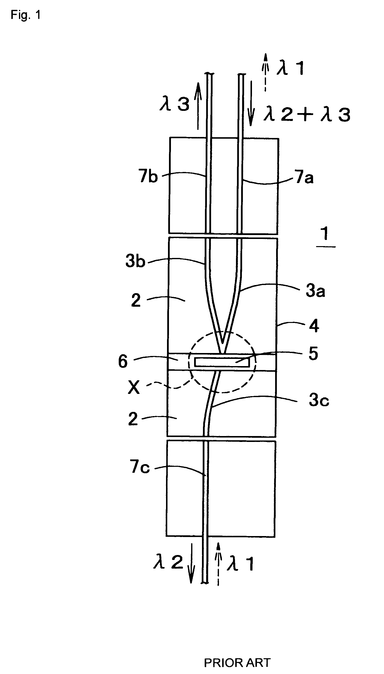
When this phenomenon occurs, the light of the wavelength λ2 is mixed in the second core 3b which is provided for extracting only the light of the wavelength λ3, so that the light of the wavelength λ2 is coupled to the optical fiber 7b and becomes noise, which causes an adverse effect in which communication is hindered, for example.
Similarly, when the light of the wavelength λ1 is made incident from the optical fiber 7c onto the third core 3c, a part of the light emitted from the end face of the third core 3c and transmitting through the filter 5 is not led to the first core 3a but made incident onto the second core 3b, so that it is propagated in the second core 3b and becomes noise, which lowers communication quality in some cases.
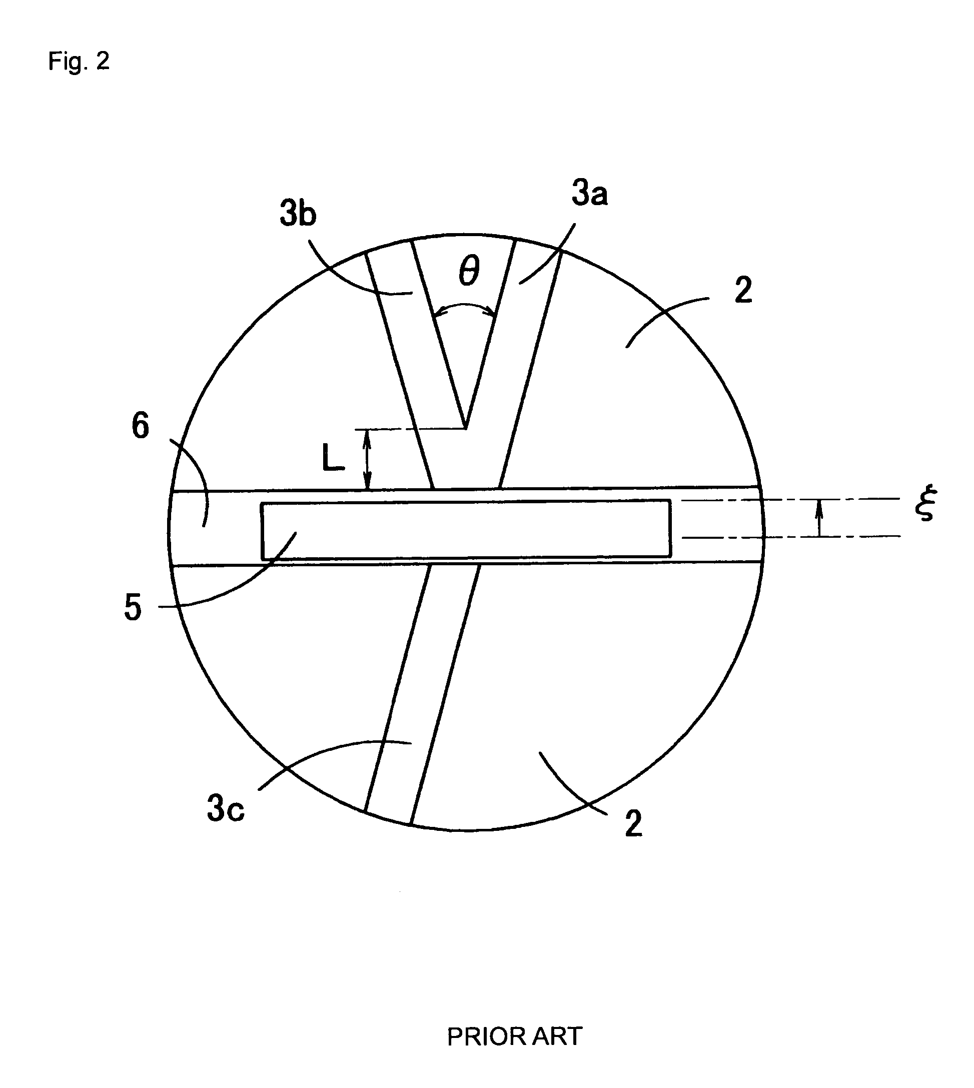
However, since a curve showing variation in loss becomes abrupt when the branching angle θ becomes large.
According to the method of increasing the branching angle θ in order to reduce the noise, therefore, loss is largely varied by a slight variation of the filter position in the groove 6, so that the required position precision of the filter 5 becomes strict and it becomes difficult to manufacture the optical multiplexer / demultiplexer.
Therefore, as the branching angle θ is increased, a length of the curved portion of each of the cores 3a and 3b has to be increased, so that the optical waveguide becomes large, cost of the optical waveguide is increased and propagation loss is also increased.

Method used


Image

  • Optical multiplexer/demultiplexer
  • Optical multiplexer/demultiplexer
  • Optical multiplexer/demultiplexer

Examples


first embodiment

(First Embodiment)

[0037]FIG. 4 shows a perspective view of an optical multiplexer / demultiplexer 11 according to a first embodiment of the present invention. In addition, FIG. 5 shows a sectional view of the optical multiplexer / demultiplexer 11 in FIG. 4 taken along optical fibers 17c and 17a and cores 13c and 13a. In the optical multiplexer / demultiplexer 11, an optical waveguide 14 and a filter element 15 are provided on an upper surface of a silicon substrate 18. In FIG. 4, the single-mode optical fibers 17a, 17b and 17c at use wavelength are connected to end faces of the cores 13a , 13b and 13c, respectively.

[0038]In the optical waveguide 14 constituting a main part of the optical multiplexer / demultiplexer 11, the cores 13a, 13b and 13c are buried in clads 12 made of a transparent plastic material or glass. The clad 12 comprises an upper clad 12a and a lower clad 12b which are overlapped with each other, and the cores 13a, 13b and 13c are sandwiched between the upper clad 12a and ...

second embodiment

(Second Embodiment)

[0066]FIG. 15 shows a perspective view of an optical multiplexer / demultiplexer 28 (WDM coupler) according to a second embodiment of the present invention. The optical multiplexer / demultiplexer 28 has a structure in which the third core 13c in the optical waveguide 14 in the optical multiplexer / demultiplexer 11 according to the first embodiment is removed. That is, according to the optical multiplexer / demultiplexer 28, a first core 13a and a second core 13b are buried in a clad 12, end faces of the cores 13a and 13b are exposed at both end faces of the clad 12, and the first and second cores 3a and 3b are connected in approximate V-shape at one end of the clad 12. A filter element 15 is provided at the end face of the clad 12 where the cores 13a and 13b are connected in the approximate V-shape, and the end faces of the first and second cores 13a and 13b are opposed to the filter element 15.

[0067]Optical fiber blocks 29 and 30 are connected to both ends of the optic...

third embodiment

(Third Embodiment)

[0072]FIG. 17 shows an optical multiplexer / demultiplexer 32 comprising a four-branching coupler according to a third embodiment of the present invention. According to the optical multiplexer / demultiplexer 32, a first core 13a and a second core 13b which are buried in a clad 12 are connected in approximate V-shape at one end of the clad 12. The core 13a branches off in two cores 13d and 13e, the core 13d branches off in two cores 13f and 13g, and the core 13e branches off in two cores 13h and 13i. In addition, a filter element 15 is bonded to the end face of the clad 12 on which the cores 13a and the core 13b are connected.

[0073]Although it is not shown, optical fiber blocks are connected to both ends of an optical waveguide 14, respectively. The optical fiber block connected to the side of the filter element 15 comprises an optical fiber 17c which is optically connected to the core 13a through the filter element 15. In addition, the optical fiber block connected to...


PUM


Abstract

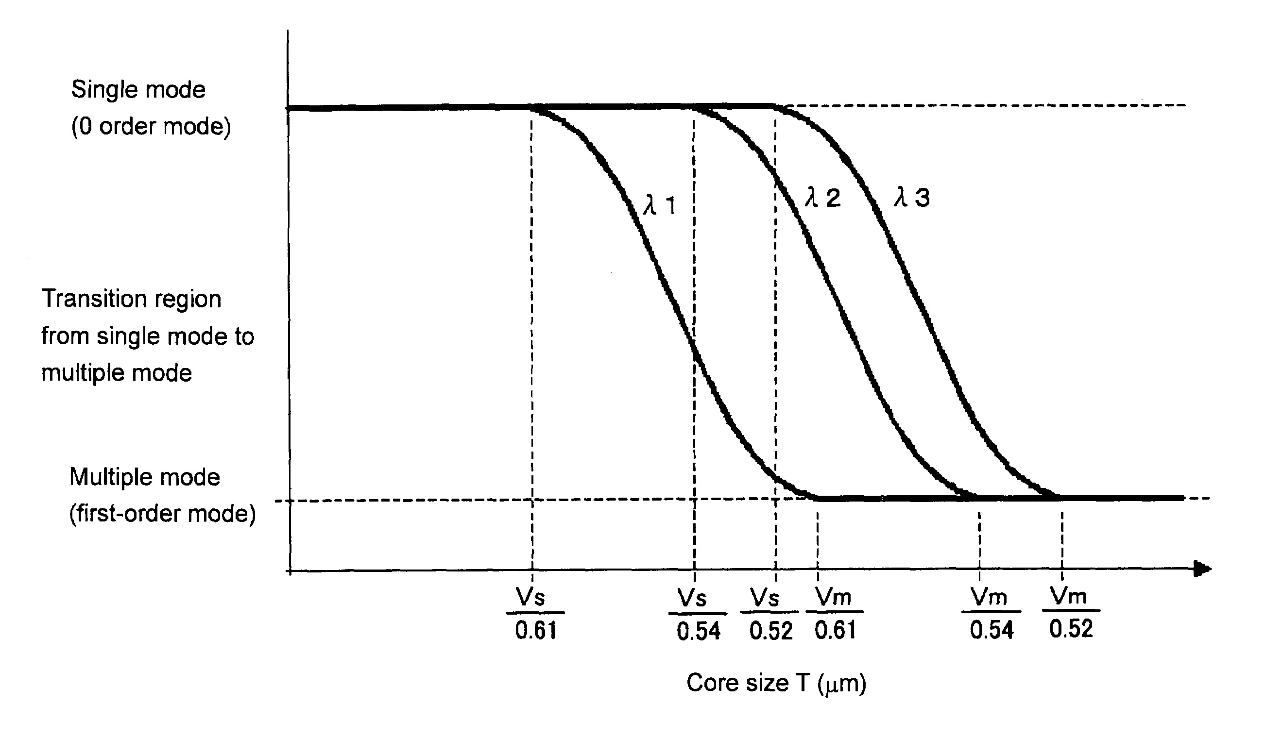
Light of wavelengths λ2 and λ3 (λ2<λ3) is propagated in a first core. The light emitted form the first core is divided at a filter. That is, the light of the wavelength λ2 transmits through the filter and is made incident onto a third core while the light of the wavelength λ3 is reflected from a filter and is made incident onto a second core. The second core has a sectional area which works in a single mode for the light of the wavelength λ3 and works in a multiple mode for the light of the wavelength λ2. It is therefore possible to prevent noise or stray light in an optical multiplexer / demultiplexer.

Description

BACKGROUND OF THE INVENTION[0001]1. Field of the Invention[0002]The present invention relates to an optical multiplexer / demultiplexer.[0003]2. Description of the Related Art[0004]Various kinds of structures of an optical multiplexer / demultiplexer have been proposed in the field of optical communications. FIG. 1 shows the structure of a conventional optical multiplexer / demultiplexer using a dielectric multilayer filter, in which a clad is cross-sectioned along a plane passing an upper face of a core. According to the optical multiplexer / demultiplexer 1, an optical waveguide 4 is constituted such that cores 3a, 3b and 3c are buried in a clad 2 made of a transparent material. In the optical waveguide 4, a groove 6 for a filter 5 such as a dielectric multilayer filter is formed, and the filter 5 is inserted in the groove 6. The first and second cores 3a and 3b are provided in the clad 2 positioned at one side of the groove 6, and are connected in the approximate V-shape at the end facin...

Claims


Application Information

Patent Timeline
Patent Type & Authority Patents(United States)
IPC IPC(8): G02B6/28H04J14/04G02B6/12G02B6/34G02B6/42
CPCG02B6/12007G02B6/29368G02B6/2938G02B6/4246G02B2006/121G02B2006/1215
Inventor TERAKAWA, YUKARIMORI, TOSHINARIHOSOKAWA, HAYAMI
Owner ORMON CORP
Learn More